CPN-UPN Communication for Support of RAN and Network Slice Attributes
CPN-UPN Communication enables traffic management based on Radio Access Network (RAN) and Network Slice attributes in the Standalone User Plane Node (UPN). This feature allows you to enable flow sampling and forward listing based on the RAN attributes and flow sampling based on the Network Slice attributes. This is achieved by establishing communication between Control Plane Node and the Standalone UPN.
The CUPS architecture provides network visibility across the control and user planes for the 5G stand-alone packet core network. The UPN processes the GTP-u traffic using the subscriber correlation from the control plane PFCP protocols available at the user plane sites. UPN enriches the subscriber information extracted from the Gigamon PFCP message (GPFCP) packets received from CPN for enhanced flow sampling and forward listing capabilities.
By establishing a communication between CPN and UPN, the RAN and the Network Slice Attributes from the CPN are exchanged with UPN, which allows UPN to flow sample and forward list the traffic based on the RAN attributes and flow sample the traffic based on Network Slice attributes.
The CPN-UPN Communication solution includes the following components:
- CPN: can be 4G or 5G
- Standalone UPN
UPN supports the following parameters based on the attributes received from CPN:
RAN flow sampling and forward listing parameters
|
o
|
E-UTRAN Cell Global Identifier (ECGI) (MCC+MNC+ECI) |
|
o
|
New Radio Cell Global Identifier (NCGI) (MCC+MNC+NCI) |
|
o
|
Tracking Area Code (TAC) |
|
o
|
Tracking Area Identity (TAI) (MCC+MNC+TAC) |
Network Slice flow sampling parameters
|
o
|
S-NSSAI with standardized SST (Slice/Service Type) |
|
o
|
S-NSSAI non-standard SST values with and without SD |

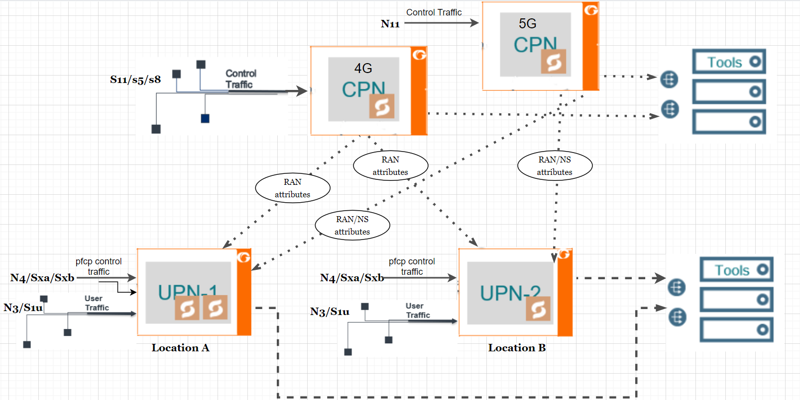
The above topology explains how CPN and UPN communicate with each other.
In the above topology, the 4G CPN receives control traffic from the S11/S5/S8 interface, while the 5G CPN receives control traffic from the N11 interface. UPN-1 and UPN-2 receive PFCP traffic from the N4/Sxa/Sxb interface. Upon receiving PFCP traffic, UPN generates a session table that does not include the RAN and Network Slice Attributes.
The communication between CPN and UPN is facilitated using the GFPCP. GPFCP messages are never fragmented, and the message exchange between CPN and UPN is always less than 1500 bytes. Once the communication is established using GPFCP, the CPN pushes the RAN and Network Slice attributes to the UPN based on a request and appends the session table with the RAN and Network Slice attributes. In case of failures, UPN can also request the RAN and Network Slice attributes from CPN.
Once the UPN receives the user traffic from N3/S1u interface, based on the map rules configured in the UPN, the correlation takes place. With the RAN and Network Slice (NS) attributes from the CPN, the UPN now has the ability to flow sample and forward list the traffic based on the RAN and Network Slice Attributes. RAN and Network Slice information is not added to the packets sent out by UPN.
Keep in mind the following when configuring CPN-UPN Communication solution:
|
■
|
UPN will back up and restore the sessions with the session attributes received from CPN. |
|
■
|
4G CPN supports only RAN Attributes. |
|
■
|
The GPFCP messages are exchanged through UDP and are not encrypted. |
|
■
|
The UDP port used for the CPN-UPN communication must be within the ephemeral range (49152 to 65535). |
|
■
|
The GPFCP messages are not fragmented. |
To know more about CPN-UPN communication configuration, communication statistics, map rules, upgrade, and rollback, refer to the following sections:


