Configuration Netflow Generation
The following are the step for setting up a typical NetFlow Generation configuration with GigaVUE-FM:
| Step 1: Configure a GigaSMART Group |
| Step 2: Configure the NetFlow Exporter |
| Step 3: Configure an IP Interface |
| Step 4: Configure the NetFlow Record |
| Step 5: Configure the NetFlow Monitor |
| Step 6: Add the NetFlow Monitor to GigaSMART Group |
| Step 7: Configure the GigaSMART Operation |
| Step 8: Configure Mapping Rules to Filter Packets |
Configure a GigaSMART Group using the following steps. you will use this GigaSMART Group in Step 6: Add the NetFlow Monitor to GigaSMART Group, where you assign a NetFlow Monitor to the group.
| 1. | From the device view, select GigaSMART > GigaSMART Groups. |
| 2. | Click New to create a new GigaSMART Group. |
| 3. | Enter an alias to help identify this GigaSMART group. For example, Netflow-gsgrp |
| 4. | Select an engine port (the e port references the GigaSMART line card or module) Your GigaSMART group should look similar to the example shown in the following figure. |
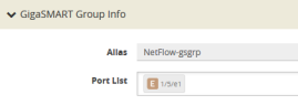
| 5. | Click Save. |
Notes:
| The GigaSMART Group can contain multiple GigaSMART engine ports. |
| Only one NetFlow Generation Monitor can be configured per GigaSMART Group. |
| Once a GigaSMART group is created, the Alias and port List values are no longer modifiable. You will need to recreate the group to change these values. |
Configure one or more NetFlow Generation Exporters. There can be up to six NetFlow Generation Exporters for each NetFlow Generation Monitor.
To access GigaSMART within GigaVUE-FM, access a device that has been added to GigaVUE-FM from the GigaVUE-FM interface. GigaSMART appears in the navigation pane of the device view on supported devices. Refer to the Access GigaSMART from GigaVUE‑FM for details.
To configure the NetFlow Exporter, do the following:
| 1. | From the device view, select GigaSMART > NetFlow / IPFIX Generation > Exporters. |
| 2. | Click New. The NetFlow Exporters page appears. |
| 3. | On the NetFlow Exporter page, enter the information for the exporter. Table 1: NetFlow ExporterConfiguration Fields describes the fields. |
Note: The NetFlow version must be configured with the same version of the Exporter and the Record. If no version is specified, version 9 is the default.
| 4. | Under the Filters section, click Add a Rule to create a filter for the exporter. |
| 5. | Click Save. |
|
Field |
Description |
|
Alias |
The alias name for the NetFlow Exporter. |
|
Description |
An optional description of the NetFlow record. |
|
Format |
The format is either NetFlow or CEF. |
|
Version |
The version is either NetFlow-v9, NetFlow-v5, or IPFIX. |
|
Template Refresh Interval |
After each template-refresh-interval, the record template is sent to the collector. Also, the option template is sent. |
|
SNMP |
Enables SNMP packet support on IP interfaces associated with the NetFlow Exporter. |
|
Transport Protocol |
The UDP port of the collector. This value cannot be changed. |
|
IP Version |
IP Version of the destination IP. You can select IPv4 or IPv6. Default is set as v4. |
|
Destination IP |
The IP address of the NetFlow/IPFIX collector. Default is set as 0.0.0.0. |
|
Destination Port |
Port for the destination IP. Default is set as 2055. |
|
DSCP |
The DSCP priority of the packet. Default is set as 0. |
|
TTL |
The Time to Live of the packet. Default is set as 64. |
In this step, you identify the collector port and configure it as a tool port, where the NetFlow collector will be connected, and then configure an IP interface. The steps are as follows:
| 1. | Select the port to use and configure it as a tool port. |
| a. | Select Ports > Ports > All Ports. |
| b. | Click the Quick Port Editor button to open the Quick Port Editor. |
| c. | In the Quick Port Editor select the port to use for the IP interface, provide an alias to help identify the port (for example, NetFlow_Tunnel_Port), select Tool for the port type, and select Enable. |
| d. | Click OK. |
| 2. | Select Ports > IP Interfaces. |
| 3. | Click New. |
| 4. | On the IP Interface page, do the following: |
| a. | In the Alias and Description fields, enter a name and description for the IP interface. |
| b. | From the Port drop-down list, select the tool port that you configured in Step 1. |
| c. | Select the type of IP interface as either IPv4 or IPv6. |
| d. | Enter the IP Address, IP Mask, Gateway address, and MTU value. |
| e. | From the GigaSMART Group drop-down list, select the GigaSMART group you created in Step 1: Configure a GigaSMART Group. |
| f. | From the Exporters drop-down list, select the NetFlow exporter you created in Step 2: Configure the NetFlow Exporter. |
Configure a NetFlow Generation Record that has the following:
| match parameters that identify unique flows |
| collect parameters that identify fields you want to collect for the unique flows |
To access GigaSMART within GigaVUE-FM, access a device that has been added to GigaVUE-FM from the GigaVUE-FM interface. GigaSMART appears in the navigation pane of the device view on supported devices. Refer to the Access GigaSMART from GigaVUE‑FM for details.
To configure the NetFlow Record, do the following:
| 1. | From the device view, select GigaSMART > NetFlow / IPFIX Generation > Records. |
| 2. | Click New. The NetFlow record page shown in 2 displays. |
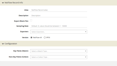
| 2 | NetFlow Record Page |
| 3. | On the NetFlow Record page, do the following: |
|
Field |
Description |
|
Alias |
The alias name that would help identify the NetFlow record. |
|
Description |
An optional description of the NetFlow record. |
|
Sampling Rate |
The Sampling Rate is multi-rate only, and is specified as 1 in N, where N is the packet count. The packet count can be a number from 1 to 16000. Refer to Configuration Netflow Generation. The Sampling Rate is disabled by default. |
|
Exporter |
Select the Exporter that you want from the Exporters menu. |
|
Version |
The version is either NetFlow-v9 or IPFIX. The NetFlow version must be configured with the same version of the Exporter and the Record. NetFlow-v9 is the default. NetFlow-v9 and IPFIX let you configure Match/Key and Collect/Non-Key elements. Make sure that you configure the NetFlow version prior to configuring the match and collect parameters because the subsequent parameters depend on the NetFlow version configured. |
|
Key Fields (Match) |
The parameters that identify unique flows. The available Match/Key fields are based on the configured NetFlow version. |
|
Non-Key Fields (Collect) |
The parameters that identify what you want to collect for the unique flows. The number of Collect/Non-Key elements in a record can be up to 32. From the drop down select the following option: Exporter- You can collect IPv4 or IPv6 switch management interface address by including additional collects in their configuration. You can select any of the following options: IPv4 address—Adds new switch or router management IPv4 address. IPv6 address—Adds new switch or router management IPv6 address. For details about the match and collect parameters, refer to Configuration Netflow Generation |
Configure a NetFlow Generation Monitor and associate the NetFlow Generation Record to the specified NetFlow Generation Monitor by doing the following:
| 1. | From the device view, select GigaSMART > NetFlow / IPFIX Generation > Monitors. |
| 2. | Click New. The Monitors page displays. |
| 3. | On the Monitors page, do the following: |
| a. | Enter an Alias to identify the monitor. |
| b. | Enter a Description (optional). |
| c. | Configure the Cache parameters. Refer to Table 4: NetFlow Monitor Parameters. |
| d. | Configure the Sampling parameters. Refer to Table 4: NetFlow Monitor Parameters. |
| e. | Select the Record that you configured in Step 4: Configure the NetFlow Record. |
| 4. | Click Save. |
|
Parameter |
Description |
|||||||||
|
Cache Type |
Set as Normal. |
|||||||||
|
Cache Timeout Active |
Despite the flow being active, it is “flushed out” to the Exporter after this timeout, which is set in seconds. |
|||||||||
|
Cache Timeout Inactive |
Inactive flows are “flushed out” to the Exporter after this timeout, which is set in seconds. |
|||||||||
|
Cache Timeout Event |
Applies to the TCP flow. The flow is “flushed out” to the Exporter after detecting a FIN or RST. |
|||||||||
|
Mode |
Select the sampling mode that you want:
|
|||||||||
|
Single Sampling Rate |
Refer to Configuration Netflow Generation. |
Return to the GigaSMART Group configured in Step 1: Configure a GigaSMART Groupand set the NetFlow Monitor to the monitor created in Step 2: Configure the NetFlow Exporter.
| 1. | From the device view, select GigaSMART > GigaSMART Groups> GigaSMART Groups. |
| 2. | Select the GigaSMART Group configured inStep 1: Configure a GigaSMART Group, and then click Edit. |
| 3. | Under GigaSMART Parameters, go to NetFlow. Click in the Monitor field and select the NetFlow monitor configured in Step 5: Configure the NetFlow Monitor as shown in the following figure. |
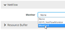
| 4. | Click Save. |
Define a GigaSMART operation to enable NetFlow Generation. If combining NetFlow with APF or De-duplication GSOPs, make sure that you select both operations when creating the GigaSMART Operation.
To access GigaSMART within GigaVUE-FM, access a device that has been added to GigaVUE-FM from the GigaVUE-FM interface. GigaSMART appears in the navigation pane of the device view on supported devices. Refer to the Access GigaSMART from GigaVUE‑FM for details.
To configure the GigaSMART Operation, do the following:
| 1. | From the device view, select GigaSMART > GigaSMART Operations (GSOP). |
| 2. | Click New. The GigaSMART Operations (GSOP) page displays. (Refer to 6.) |
| 3. | On the GigaSMART Operations page, do the following: |
| a. | In the Alias field, enter a alias to help identify this gsop. |
| b. | In the GigaSMART Groups field, select the gsop configured in Step 1: Configure a GigaSMART Group. |
eIn the GigaSMART Operations (GSOP) field, select NetFlow. The NetFlowGigaSMART Operation is enabled by default as shown in 6.
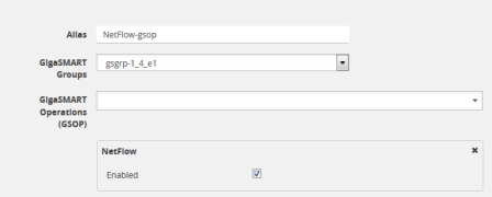
| 6 | GigaSMART Operation (GSOP) Page |
| 4. | Click Save. |
To add Flow Mapping® rules to filter packets that are needed to run NetFlow, configure a map and associate the map to the IP interface with tool port.
For more detailed information about Flow Mapping®, refer to About Flow Mapping® and Manage Maps.
Notes:
| For a single NetFlowGigaSMART Operation, make sure that you create a Regular By Rule map. When combining with APF or De-duplication, use First Level or Single Level map types. |
| Make sure that the other combining GigaSMART Operations are configured before creating maps using NetFlow. |
| When combining NetFlow with APF or De-duplication, create virtual ports to use with the second level maps. |
| The destination tool port must be the IP interface with tool port identified in Step 3: Configure an IP Interface |
For second level maps, you will need to create virtual ports. To create virtual ports, do the following:
| 1. | From the device view, select GigaSMART > Virtual Ports. |
| 2. | Click New. The Virtual Ports page displays. |
| 3. | Enter an alias in the Alias field to identify the virtual port. |
| 4. | In the GigaSMART Groups field, select the GigaSMART Group configured in Step 1: Configure a GigaSMART Group. |
| 5. | Click Save. |
To configure mapping rules to filter packets, do the following:
| 1. | Select Maps > Maps > Maps. |
| 2. | Click New to create a new map. |
| 3. | On the New Map page, do the following: |
| a. | Enter an alias in the Alias field and select the map Type and Subtype. |
| b. | Specify Source and Destination ports. |
| c. | In the GigaSMART Operations (GSOP) field, select the GigaSMART Operation configured in Step 7: Configure the GigaSMART Operation. |
| d. | Click Add a Rule to add the rules needed for the map. |
| 4. | Click Save. |


