Add Applications to Monitoring Session
GigaVUE Cloud Suite with GigaVUE V Series Node supports the following GigaSMART applications in the GigaVUE-FM canvas:
You can also configure the following GigaSMART operations from the Traffic > Solutions > Application Intelligence:
| Application Metadata Intelligence |
| Application Filtering Intelligence |
For the detailed list of GigaSMART Operation supported for GigaVUE V Series Nodes, refer to Supported GigaSMART Operations .
You can optionally use these applications to optimize the traffic sent from your instances to the monitoring tools. Refer to the Base Bundles section for more information on Licenses for using GigaVUE V Series Nodes.
To add a GigaSMART application:
- Drag and drop an application from APPLICATIONS to the canvas.
- In the canvas, click the application and select Details.
- Enter or select the required values for the selected application and click Save.
Slicing
Packet slicing lets you truncate packets after a specified header and slice length, preserving the portion of the packet required for monitoring purposes. For detailed information on Slicing, refer to GigaSMARTPacket Slicing .
To add a slicing application:
- Drag and drop Slicing from APPLICATIONS to the graphical workspace.
- Click the Slicing application and select Details. The Application quick view appears.
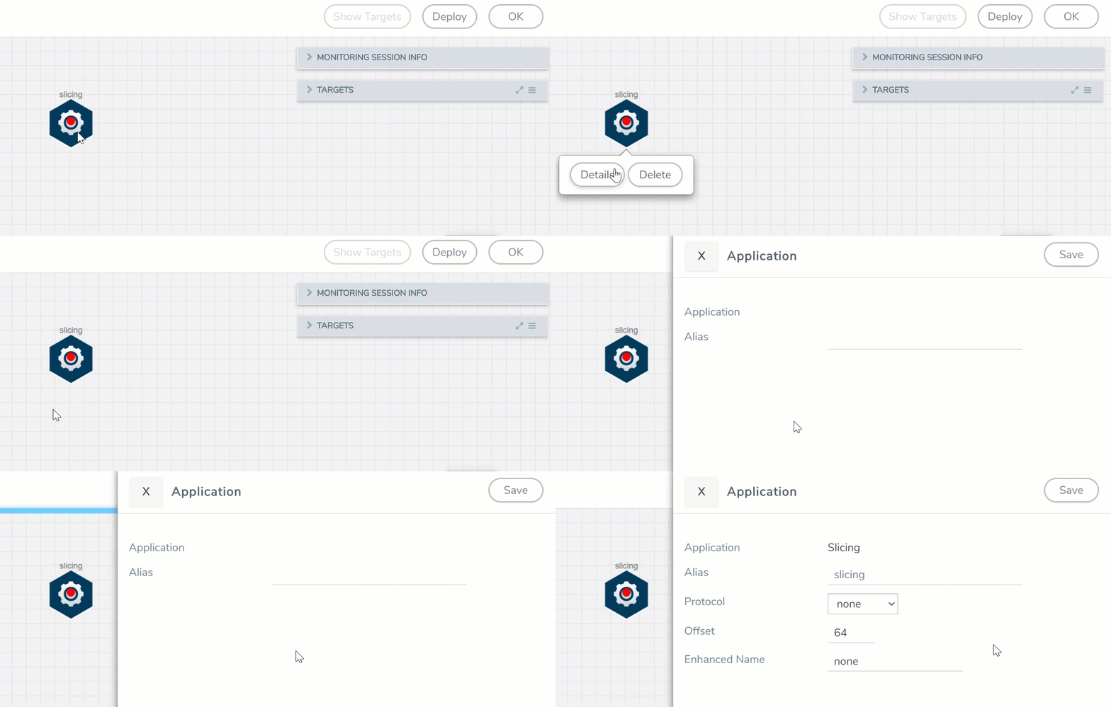
- In the Application quick view, enter the information as follows:
- In the Alias field, enter a name for the slicing.
- From the Protocol drop-down list, specify an optional parameter for slicing the specified length of the protocol.
- In the Offset field, specify the length of the packet that must be sliced.
- In the Enhanced Name field, enter the Enhanced Slicing profile name.
- Click Save.
Masking
Masking lets you overwrite specific packet fields with a specified pattern so that sensitive information is protected during network analysis. For detailed information on masking, refer to GigaSMART Masking.
To add a masking application:
- Drag and drop Masking from APPLICATIONS to the graphical workspace.
- Click the Masking application and select Details. The Application quick view appears.
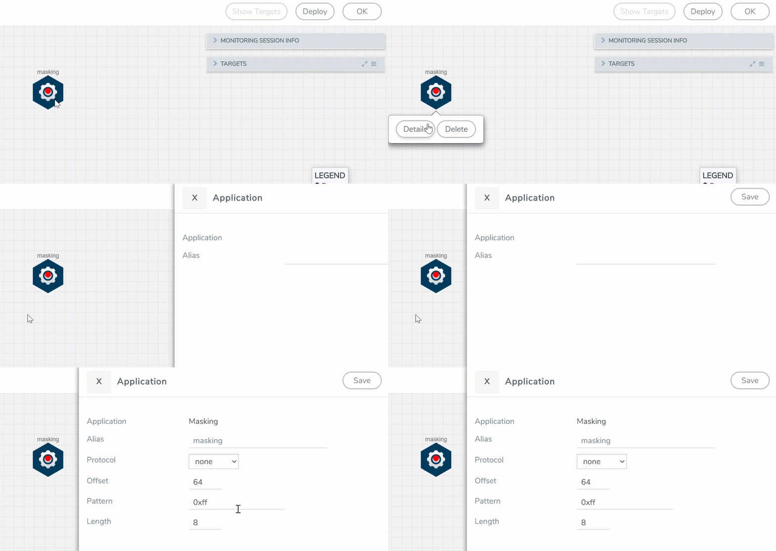
- In the Application quick view, enter the information as follows:
- In the Alias field, enter a name for the masking.
- From the Protocol drop-down list, specify an optional parameter for masking the specified length of the protocol.
- In the Offset field, specify the length of the packet that must be masked.
- In the Pattern field, enter the pattern for masking the packet.
- In the Length field, enter the length of the packet that must be masked.
- Click Save.
Dedup
De-duplication lets you detect and choose the duplicate packets to count or drop in a network analysis environment. For detailed information on de-duplication, refer to GigaSMART De-Duplication.
To add a de-duplication application:
- Drag and drop Dedup from APPLICATIONS to the graphical workspace.
- Click the Dedup application and select Details. The Application quick view appears.
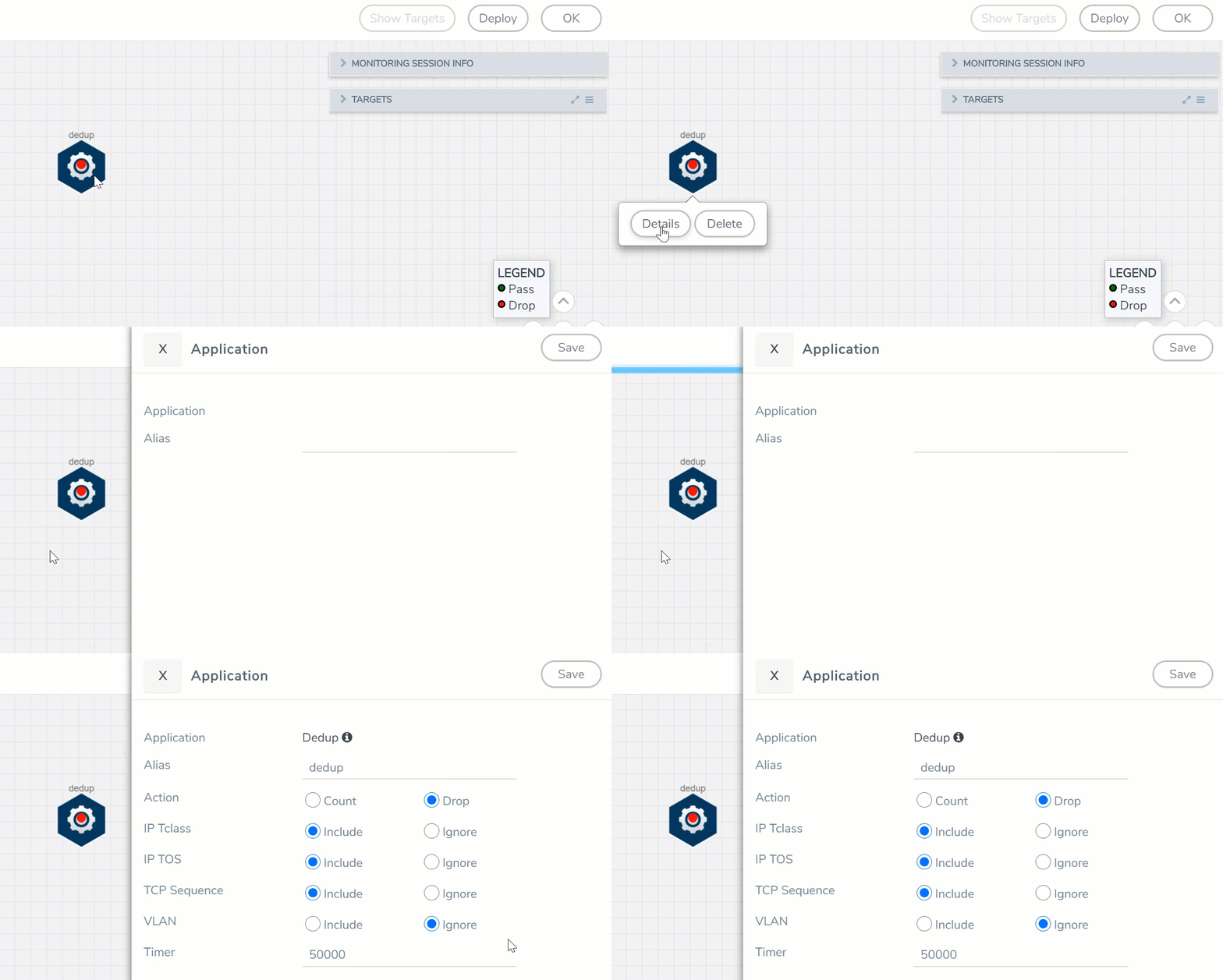
- In the Application quick view, enter the information as follows:
- In the Alias field, enter a name for the de-duplication.
- In the Action field, select Count or Drop the detected duplicate packets.
- For IP Tclass, IP TOS, TCP Sequence, and VLAN fields, select Include or Exclude the packets for de-duplication.
- In the Timer field, enter the time interval (in seconds) for de-duplicating the packet.
- Click Save.
Load Balancing
Load balancing app performs stateless distribution of the packets between different endpoints. For detailed information on load balancing, refer to GigaSMART Load Balancing .
To add a load balancing application:
- Drag and drop Load Balancing from APPLICATIONS to the graphical workspace.
- Click the load balancing application and select Details. The Application quick view appears.
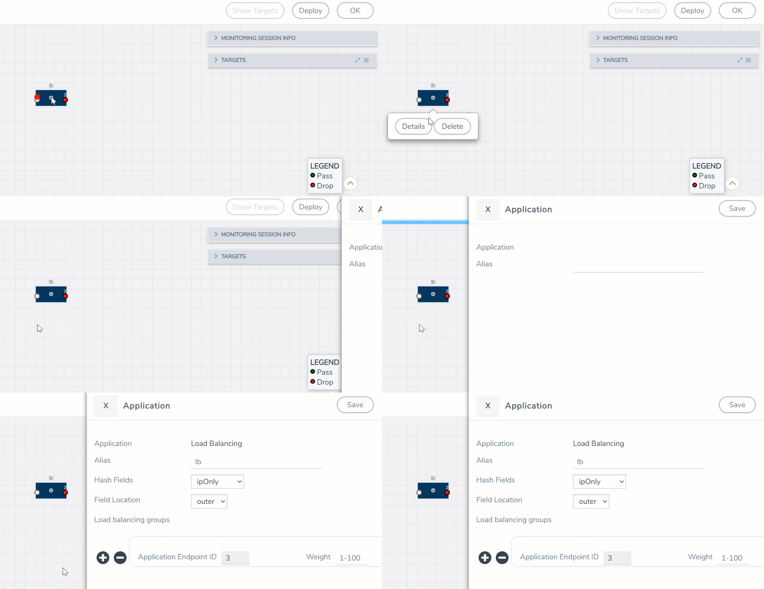
- In the Application quick view, enter the information as follows:
- In the Alias field, enter a name for the load balancing app.
- For Hash Fields field, select a hash field from the list.
- ipOnly—includes Source IP, and Destination IP.
- ipAndPort—includes Source IP, Destination IP, Source Port , and Destination Ports.
- fiveTuple—includes Source IP, Destination IP, Source Port, Destination Port, and Protocol fields.
- gtpuTeid—includes GTP-U.
- For Field location field, select Inner or Outer location.
Note: Field location is not supported for gtpuTeid.
- In the load balancing groups, add or remove an application with the Endpoint ID and Weight value (1-100). A load balancing group can have minimum of two endpoints.
- Click Save.
PCAPng
The PCAPng application is a GigaSMART parser application that reads the various blocks in the received PCAPng files and validates the blocks to be sent to the destination application or to the tools.
Note: The PCAPng application is only applicable for the Ericsson 5G Core vTAP architecture. Refer to PCAPng Application for detailed information.
Create Link Between UDP-in-GRE Tunnel and PCAPng Application
To create a link with source as UDP-in-GRE tunnel and destination as PCAPng application:
- In the GigaVUE‑FM canvas, select New > New Tunnel, drag and drop a new tunnel template to the workspace. The Add Tunnel Spec quick view appears.
- On the New Tunnel quick view, enter or select the required information as described in the following table.
Field
Description
Alias
The name of the tunnel endpoint
Note: Do not enter spaces in the alias name.
Description
The description of the tunnel endpoint
Type
Select UDPGRE as the tunnel type
Traffic Direction
The direction of the traffic flowing through the V Series node
- Choose In (Decapsulation) for creating an Ingress tunnel, traffic from the source to the V Series node
IP Version
The version of the Internet Protocol. Select IPv4 or IPv6
Remote Tunnel IP
The IP address of the tunnel source
Key
GRE key value
Source L4 Port
Layer 4 source port number
Destination L4 Port
Layer 4 destination port number. You can configure only 4754 or 4755 as the destination UDP ports
- Click Save.
- Click and drag the PCAPng application into the canvas. Configure the alias for the application.
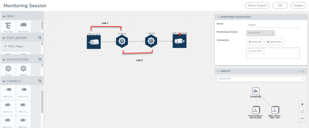
- Establish a link between the UDP-GRE TEP configured above and the PCAPng application.
Create Link Between PCAPng Application and Other Destinations
Create a link with source as PCAPng application and destination as one of the following:
- Other GigaSMART applications such as Slicing, Masking, etc.
- Other encapsulation TEPs.
- REP/MAP
Refer to the following image for a sample configuration.
