Resilient Inline Arrangement with GigaSMART Flex Inline Solution
GigaSMART Flex Inline Solution can now be configured in a Resilient Inline Arrangement (RIA). It is supported on all GigaVUE HC Series devices. To learn more about Resilient Inline Arrangements refer to Configure Resilient Inline Arrangement.
A resilient inline arrangement uses two nodes for traffic management of dual-path high availability environments. The nodes will process traffic at the same time using source and destination IP. For traffic received from the top network interfaces are decided based on the source IP, whereas the traffic received from bottom network interfaces use the destination IP of incoming traffic. If the IP address end with an even number, then the traffic will be forwarded to one node whereas if it is an odd number then it will be sent to another node.
For example:
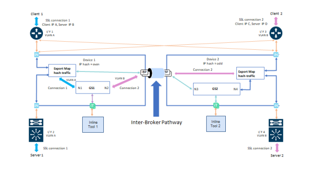
In the below Resilient Inline Arrangement , interface (I/F) 1 and I/F 2 are connected to node 1, I/F 3 and I/F 4 are connected to node 2. For connection 1 client 1, traffic from I/F 1 with VLAN A source, IP A will be forwarded to GS1 in node 1 since last decimal digit of IP A is even. The Traffic of server 1 of the same connection from I/F 2 with VLAN A destination IP A will also be forwarded to GS1 in node 1. Since last digit of IP C is even, connection 2 traffic from I/F 3 and I/F 4 will also be forwarded to GS1 in node 1. Connection 2 traffic between GS1 and client 2 will be on I/F 3 with VLAN B, these packets need to pass through IBP connected between node 1 and node 2. Similarly, traffic between GS1 and server 2 will be on I/F 4 after passing through IBP.

Symmetric Traffic in RIA
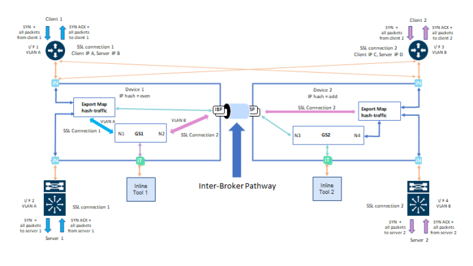
In a Symmetric connection the SYN packet from client 1 is received on I/F 1 with VLAN A. This incoming SYN packet is forwarded to GS1 in node 1 since source IP (IP A) is even. GS1 will initiate TCP connection to server 1 by sending SYN packet out from I/F 2 with VLAN A as shown below.
Server 1 responds SYN ACK from I/F 2 with VLAN A and the packet is forwarded to GS1 since destination IP (IP A) is even. All inbound and outbound traffic between GS1 and client 1 will be on I/F 1 and all traffic between GS1 and server 1 will be on I/F 2 attached to node 1. Similarly, traffic from connection 2 on I/F 3 and I/F 4 with VLAN B are processed by GS1 on node 1 since client 2 IP (IP C) is even. All traffic between GS1 and client 2 will be on I/F 3 with VLAN B through IBP and all traffic between GS1 and server 2 will be on I/F 4 with VLAN B attached to node 2.

Asymmetric Traffic in RIA
An asymmetric connection can occur in the following scenarios:
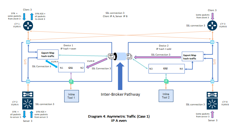
| 1. | Let's consider the below resilient inline arrangement ,the SYN packet of TLS/SSL connection 3 from client 3 is received on I/F 1 with VLAN A. This incoming SYN packet is forwarded to GS1 in device 1 since source IP (IP A) is even. Server 3 responds SYN ACK from I/F 2 with VLAN A on device 1 and the packet is forwarded to GS1 since destination IP (IP A) is even. After that, GS1 will send SYN ACK to client 3 on I/F 1 with VLAN A.. Due to asymmetric routing or load balancing, some subsequent client or server traffic of connection 3 may arrive at I/F 3 or I/F 4 with VlAN B which is then forwarded to node 1 through IBP. This is to achieve symmetric inspection of traffic at the same tool. Regardless of incoming traffic interface, all outgoing traffic from GS1 to client 3 will be sent in I/F 1 with VLAN A and from GS1 to server 3 will be sent in I/F 2 with VLAN A. |

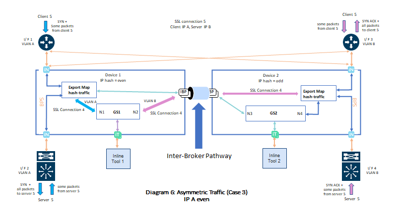
| 2. | Consider the below arrangement wherein, the SYN packet of TLS/SSL connection 5 from client 5 is received on I/F 1 with VLAN A and it is forwarded to GS1 in node 1 since source IP (IP A) is even. GS1 will initiate TCP connection to Server 5 attached to node 1 by sending SYN packet out from I/F 2 with VLAN A . Server 5 responds SYN ACK from I/F 4 with VLAN B on node 2 and the packet is forwarded to GS1 through IBP since destination IP (IP A) is even. As SYN ACK is received from server 5 on I/F 4 with VLAN B in node 2, GS1 will send SYN ACK to client 5 on I/F 3 with VLAN B connected to node 2. Due to asymmetric routing or load balancing, some subsequent incoming traffic from client 5 may arrive I/F 3 with VLAN B on device 2, these incoming traffic will be forwarded to GS1 through IBP since source IP (IP A) is even. Similarly, some subsequent incoming server 5 traffic may arrive at I/F 2 with VLAN A on node 1. These traffic will also be forwarded to GS1 on node 1 since the destination IP (IP A) is even .The outgoing traffic from GS1 to client 5 will be on I/F 3 with VLAN B attached to node 2 and all outgoing traffic from GS1 to server 5 will be on I/F 2 with VLAN A attached to node 1 regard less of the incoming traffic interface. |

Setup Resilient Inline TLS/SSL
To configure and deploy Resilient Inline TLS/SSL , ensure the following prerequisites are done for the nodes such as:
| 1. | Configure the required inline networks. Refer to Configure Inline Network Ports and Inline Network. |
| 2. | Configure the required inline tools. Refer to Configure Inline Tool Ports and Inline Tools. |
| 3. | Configure the required inline tool group. Refer to Configure Inline Tool Group. |
| 4. | Create Inter-broker Pathway Refer to Configure Resilient Inline Arrangement |
| 5. | Click on |
| Begin with configuring the Inline TLS/SSL App alias name. |
| Enable Resilient Inline Arrangements checkbox. |
| Select the nodes that would be configured and the respective GigaSMART modules. |
| Click on Add Keys under Deployment Type, to configure Key Store Certificates .The keys added will be pushed to both nodes. To delete the key you will have to do so from individual nodes. |
| Configure the Inline TLS/SSL profile fields for decryption and click on OK. For details about the Inline TLS/SSL Policy Profile fields and their descriptions, refer to Inline TLS/SSL Policy Profile—Field References in Configure Inline TLS/SSL Decryption Using GigaVUE‑FM. |
| You can configure Inline SSL App for any one of the nodes. It will be available for the second node as well. |
Once the necessary pre-requisites are configured , in the Flexible Inline Canvas do the following:
1. Drag and drop Inline Network/Inline Network Bundle into the canvas.
2. Drag and drop a Flex map, Inline Tools and Inline SSL APP that are available on both the nodes with same alias, to configure the Flex Inline TLS/SSL maps.
3. Under the Settings option, enable the 'Show Resilient Inline Menu' checkbox and setup the Node, IB Pathway and Hashing configurations.
4. Click on Deploy.
Limitations
-
At a time only one RIA enabled TLS/SSL app will be supported for the given set of two nodes needed for Resilient Inline TLS/SSL solution.
-
A combination of RIA enabled SSL app and normal Flex SSL app(RIA disabled) is not supported and will be blocked in GigaVUE- FM. If the node has a normal flex TLS/SSL app, you cannot add an RIA enabled TLS/SSL app and vice-versa.
-
Inline SSL apps in GigaSMART Flex Inline Solutions can be modified by removing the existing TLS/SSL app from all the solutions and deploying the same, followed by adding or replacing the TLS/SSL apps.
-
Inline-tool with shared mode false is not supported.
-
GigaSMART Flex Inline Solution and single VLAN Tag feature will not be supported.
-
Inline NetLag as a source is not supported.
-
Editing tool side VLAN tag is not allowed.
-
Using protected ports (BPS ports) in would result half of the traffic to be un-inspected in case of node failure.
-
One-arm topology is not supported.
-
Tool early-engage is not supported.
-
Inline classic MAPs will not be supported.
-
Iboss and resilient hashing are not supported.
-
Cluster is not supported.
Refer the following Gigamon Validated Designs for more detailed information:


