Configure ICAP Client for Inline TLS/SSL Decryption Solution
This section provides topics on configuring and using ICAP Client for Inline TLS/SSL Decryption Solution.
Prerequistes
|
■
|
Allocate two separate GigaSMART engines—one dedicated to Inline SSL and one to ICAP—and if HTTP/2 downgrade is required in Inline SSL, use Gen3 devices for both engines. |
|
■
|
Rely on the system to add the GigaSMART Group automatically for ICAP when the port is attached to the ICAP Client, so you do not need to add it during IP Interface creation. |
|
■
|
Gather the ICAP server details, including IP/hostname and listening port (typically 1344), plus any required service URIs (REQMOD, RESPMOD, OPTIONS). |
|
■
|
Decide on the deployment type—Same Node or Different Node—and for Same Node be prepared to select the Inline SSL Inline Tool as the ICAP Client’s Source port, while for Different Node you must ensure a network interconnect carries the clear‑text feed from the Inline SSL node to the ICAP node’s Inline Network. |
|
■
|
Verify compatibility constraints beforehand, because the ICAP Client cannot be deployed inline with One‑Arm iSSL, L3 NAT iSSL, or RIA iSSL. |
Access Flexible Inline Canvas
|
1.
|
Go to  > Physical > Orchestrated Flows > Inline Flows > Configuration Canvas to create a new Flexible Inline Canvas. > Physical > Orchestrated Flows > Inline Flows > Configuration Canvas to create a new Flexible Inline Canvas. |
|
2.
|
In the displayed Flexible Inline Canvas, select the device where you want to configure the TLS/SSL decryption. |
Configure Inline Network
For an Inline SSL with ICAP deployment, create the Inline SSL constructs (one Inline Network with NA/NB legs and an Inline Tool) and a separate Inline Network for ICAP, then configure an IP Interface on a tool port with the required IP/subnet/gateway/VLAN to reach the ICAP server.
|
1.
|
On the left pane, click the ‘+’ icon next to Inline Network option to create a new entry. |
|
2.
|
Enter a name and description for the inline network in the Alias and Description fields. Then, click Port Editor. |
|
3.
|
In the Alias and Description fields, enter a name and description for the inline network. |
|
4.
|
Click Port Editor. In the Quick Port Editor, scroll down to the inline network ports that you want to configure. Select Enable to administratively enable inline network ports, and click OK to apply the changes. |
|
5.
|
From the Port A and Port B drop-down lists, select the ports that you want to configure as the inline network pair. |
|
6.
|
From the Traffic Path drop-down list, select To Inline Tool. |
|
o
|
To Inline Tool—All traffic originating from the inline network is directed to the sequence of inline tools and inline tool groups and is guided through the inline tools and inline tool groups according to the current inline tool and inline tool group status.
|
|
7.
|
Click OK. You have successfully created an Inline Network. |
To explore additional options during configuration, refer to Inline Network Ports and Inline Network.
Configure Inline Tool
|
1.
|
On the left pane, click the ‘+’ icon next to the Inline Tool option to create a new inline tool. |
|
2.
|
In the Properties pane, in the Alias and Description fields, enter a name and description for the inline tool. |
|
3.
|
From the Type drop-down list, select one of the following options: |
|
o
|
External- To configure a third-party tool. |
|
o
|
GigaVUE Node- To configure a GigaVUE node as a tool. |
|
4.
|
Click Port Editor. In the Quick Port Editor, scroll down to the inline tool ports that you want to configure. Select Enable to administratively enable the inline tool ports, and then click OK to apply the changes. |
|
5.
|
From the Port A and Port B drop-down lists, select the inline tool ports according to the direction the inline tool expects traffic from the network. |
|
6.
|
Verify that the Enabled check box is selected. |
|
7.
|
Click OK. You have successfully created an Inline Network. |
To explore additional options during configuration, refer to Inline Tool Ports and Inline Tools.
Configure IP Interface
|
1.
|
On the left pane, click the ‘+’ icon next to the IP Interface option to create a new IP Interface. |
|
2.
|
In the Alias and Description fields, enter a name and description for the IP Interface. |
|
3.
|
From the Port drop down list, select the port that is connected to Network and has reach ability to the ICAP server. |
|
4.
|
Select the Type of the IP Interface that you want to configure. |
|
5.
|
Enter an IP Address. For example, 192.168.1.20. |
|
6.
|
Enter an IP Mask. For example, 255.255.255.0. |
|
7.
|
Enter a Gateway. For example, 192.168.1.20. |
|
8.
|
Enter the Maximum Transmission Unit (MTU) for this port in the MTU field. For example, 1500. |
|
9.
|
Click OK to save the configuration. |
Note: For ICAP, it is not necessary to add GS Groups when configuring IP interface. It will be added automatically when the port is added to ICAP Client.
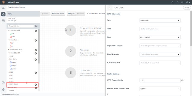
Configure ICAP Client
In an Inline TLS /SSL Decryption Solution with an ICAP Client the main choice for your ICAP configuration is :
|
■
|
Type should be either Same Node or Different Node |
To configure the ICAP Client:
|
1.
|
Go to > Physical > Orchestrated Flows > Inline Flows > Configuration Canvas to create a new Flexible Inline Canvas. |
|
2.
|
In the displayed Flexible Inline Canvas, select the device where you want to configure the ICAP Client. |
|
3.
|
Click the ‘+’ icon next to the ICAP Client to create a new entry. |
|
4.
|
Enter a name and description for the inline network in the Alias and Description fields. |
|
6.
|
Select one from the following: |
|
o
|
If ICAP and iSSL are integrated and deployed on the same node, select the Same Node option. |
|
o
|
If ICAP and iSSL are integrated and deployed on different node, select the Different Node option. |
|
7.
|
Select the required tool port of Inline SSL profile, which is connected to the inline network of ICAP. (This option will not appear if you select standalone as type.) |
|
8.
|
Click Apply to save the configurations. |
Create an Inline SSL APP
|
1.
|
On the left pane, click the ‘+’ icon next to the Inline SSL APP option. |
|
2.
|
Enter a name for the Inline SSL APP and select the required GigaSMART engines. |
|
3.
|
ICAP configuration is supported in Inbound, Outbound, and Hybrid deployment types. Select the required deployment type. Refer to TLS/SSL Sessions for more details. |
|
o
|
Outbound - Add the configured primary and a secondary signing Certificate Authorities (CA). |
|
o
|
Inbound - Add a new Server Key Mapping. Enter the domain name or IP address of the server, and then select the required Key Pair Alias. |
|
o
|
Hybrid - Add a new Server Key Mapping, and a primary and a secondary signing CA. |
|
4.
|
Under Configurations, for Default Action select one of the following options: |
|
o
|
Decrypt—Decrypt all the traffic that is guided into the Inline SSL APP. |
|
o
|
No Decrypt—Do not decrypt the traffic that is guided into the Inline SSL APP. |
|
5.
|
For URL Cache Miss Action, select one of the following options: |
|
o
|
Decrypt—Decrypt all the traffic that is guided into the Inline SSL APP. |
|
o
|
No Decrypt—Do not decrypt the traffic that is guided into the Inline SSL APP. |
|
o
|
Defer—Delay the decryption until the Defer Timeout seconds provided. |
|
6.
|
Under Security Expectations, choose to either decrypt or drop the traffic for the following certificates: |
|
o
|
Self-signed certificate |
|
7.
|
Under Network Access, select DHCP or IP Address as the network access configuration mode. If you select IP Address as the mode, enter the IP Address, Netmask, Gateway, DNS, MTU, and VLAN. |
Note: It is recommended to use static IP address option when configuring ICAP Client.
|
8.
|
Click OK. You have successfully created the Inline SSL APP.
|
To explore additional options during configuration, refer to Inline SSL App—Field References .
Deploy the Inline SSL Solution
|
1.
|
Drag and drop the required inline network configured for Inline TLS/SSL into the flexible inline canvas. |
|
2.
|
Drag and drop the Flexible Inline Map into the canvas, then in the Properties pane, click Add Rule and set the rule condition to Bi-directional. |
|
3.
|
In the rule description, add the protocol as TCP. Add the required rules for the inline map, and then click OK to save the configuration. |
|
4.
|
Drag and drop the Inline SSL APP into the canvas. |
|
5.
|
Drag and drop the required inline tools configured for Inline TLS/SSL into the canvas. |
|
6.
|
Click Deploy. You get two options to select your Traffic path during Deployment . It could be either Logical Bypass or Keep as is. Select an option based on your requirement and then click OK. |
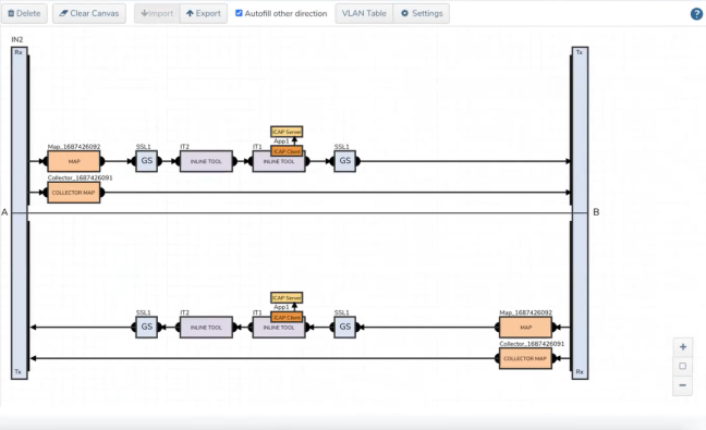
If the configuration is correct and the source ports of ICAP are properly linked to the Inline Tool port of Inline SSL, the canvas will display the inline tool indicating the ICAP client.
|
1
|
ICAP Client APP—Deployed |
Verify the Solution
|
■
|
Confirm the solution shows as Deployed on the Flexible Inline Canvas (Physical > Orchestrated Flows > Inline Flows > Configuration Canvas); ensure both Inline Networks exist: one attached to the Inline SSL app and a separate one attached to the ICAP client. |
|
■
|
Verify ICAP client wiring and health |
|
o
|
Open the ICAP client properties and confirm: |
|
•
|
The ICAP client is attached to the intended Inline Network (the ICAP‑specific inline network you created). |
|
•
|
Source Port/Interface points to the correct inline or tool port that reaches the ICAP server (as per your design). |
|
o
|
If you created an IP Interface on a tool port to reach the ICAP server, verify: |
|
•
|
IP/subnet/gateway/VLAN are correct and the interface shows Up. |
|
•
|
Basic reachability to the ICAP server (no Events/Alerts indicating ARP/route failures). |
What to Do Next
After deployment, you can view statistics details, refer to View ICAP Statistics.
|
|


