Connecting -48V DC Power Supply Modules
This section provides instructions for connecting a -48V DC input to the screw terminal on the DC power supply module.
To connect a -48V DC input to the screw terminal on the DC power supply module:
|
1
|
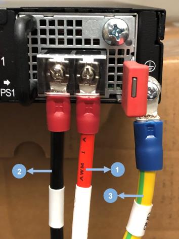
Connecting -48V DC input to the screw terminal on the DC power supply module |
|
1.
|
Connect the power supply module ground terminal (⏚) to earth ground on the left-hand side (facing the rear of the GigaVUE-TA400E). Hardware specifications for ground connection are listed below: |
|
a.
|
M6 Screw: One screw per power supply module (two modules are available in each GigaVUE-TA400E unit). |
|
b.
|
Recommended Lug: KST part number KST RVBS14-6. This lug should be 6 AWG wire. |
|
c.
|
Tightening Torque: Tighten the screw to a torque of 26.5 - 28.6 kgf-cm. |
|
2.
|
Use a Phillips screwdriver to connect both the positive and negative power cables to the screw terminals on the DC power supply module. Hardware specifications for power cables are listed below: |
|
a.
|
M4 Screws: Two screws per power supply module (each GigaVUE-TA400E has two modules). |
|
b.
|
Recommended Lug: KST part number KST RVBS8-4. This lug, designed for a maximum 8 AWG wire. |
|
c.
|
Tightening Torque: Ensure screws are tightened to a torque of 14.3 - 16.3 kgf-cm. |


