PRT-HC1-Q04X08 Module
The PRT-HC1-Q04X08 line card consists of four (4) 40Gb QSFP+ ports, four (4) 1Gb/10Gb/25Gb (X1 to X4) /SFP/SFP+/SFP28 ports and four (4) 1Gb/10Gb (X5 to X8) /SFP/SFP+ ports. This module increases the port density and allows GigaVUE-HCT to connect with GigaVUE TA Series and GigaVUE HC Series nodes with higher-speed (40Gb) links. It provides connectivity of 300Gb with line rate on-board switching across the 1Gb/10Gb/25Gb/40Gb ports. All ports in the PRT-HC1-Q04X08 module can be used as network, tool, hybrid, circuit, inline network, and inline tool ports. Moreover, the 40Gb/25Gb/10Gb ports can be used as stack-link ports.
The PRT-HC1-Q04X08 is a legacy GigaVUE-HCT line card, where the ports Q1..Q4 when inserted in GigaVUE-HCT will support 40Gb speed with the nomenclature q1..q4.
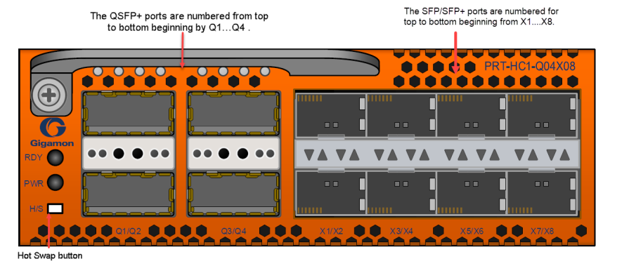
Note: when the line card PRT-HC1-Q04X08 is inserted in the GigaVUE-HCT, The ports X1..X4 will support 1Gb/10Gb/25Gb speed and the ports X5..X8 will support 1Gb/10Gb speed.
Features
| 1. | All ports, including breakout ports of this module, can be used as network, tool, hybrid, circuit, inline network and inline tool ports. The first group of four ports (x1..x4) can be configured as 25Gb. In one quad, there cannot be a mix of 10Gb and 25Gb ports. By default, all eight ports are configured as 10Gb ports. To configure 25Gb, you must configure the port speed as follows: (config) # port 1/2/x1..x4 params admin enable (config) # port 1/2/x1..x4 params speed 25000. |
| 2. | The ports can be used for 10Gb/40Gb, 4x10Gb, and 25Gb stacking. |
| 3. | The module supports 4x10Gb breakout on the 40Gb ports using SR4/PLR4/PSM4 optics. |
| 4. | The breakout ports can be used in clustering and supports IP interface configuration for netflow and tunneling. The ports in the line card can be added as part of GigaStream as well. |
| 5. | This module is hot swappable. |
For details about the supported transceiver, cable type, fan-out, inline ports, and clusters, refer to GigaVUE-OS Compatibility and Interoperability Matrix.
Module LED
The LEDs on the modules indicate the current operational status. The operational states indicated by the color of Power (PWR) and Ready (RDY) LEDs are as described below.
|
LEDs |
Color |
Description |
|---|---|---|
|
PWR - Power LED |
Solid Green |
Indicates the module is receiving power |
|
RDY - Ready LED |
Solid Green |
Indicates normal condition |
|
Solid Red |
Indicates system booting or module down |
Port Status LED
The 40Gb Port LED Q1..Q4 and 1Gb/10Gb/25Gb SFP/SFP+/SFP28 LED states are as described below:
|
LED |
Color |
Description |
|---|---|---|
|
LED Q1..Q4 |
OFF |
Port is administratively disabled, or the link is down. |
|
Solid Green |
Link up |
|
|
Port LED X1..X8 |
OFF |
Port is administratively disabled, or the link is down. |
|
Solid Green |
Link up |
|
|
Activity LED |
N/A |
Unused |


