Connecting G-TAP M Series Breakout Panels
Breakout panels are used to breakout single ports to multiple ports or to aggregate multiple ports to a single port.
There are two G-TAP M Series breakout panels available:
| PNL-M341 |
| PNL-M343 |
This section provides the following information:
| Connecting G-TAP M Series Breakout Panels |
PNL-M341 Breakout Panel Connection
The PNL-M341 is a Multimode (MM) breakout panel with a granularity of three breakouts per module. It provides three MPO ports for 40Gb/100Gb SR4 optics and 12 LC ports for 10Gb/25Gb SR optics.
Note: Purchase MPO and LC patch cables separately
The PNL-M341 breakout panel contains three breakout modules labeled A, B, and C, and can be used for the breakout of a 40Gb port to four 10Gb links or for the aggregation of four 10Gb links to a 40Gb port, or for the breakout of a 100Gb port to four 25Gb links or for the aggregation of four 25Gb links to a 100Gb port.
Refer to 1 PNL-M341 Connections for Breakout for an example of using the PNL-M341 breakout panel to breakout a single 40Gb tool port to multiple 10Gb fiber outputs.
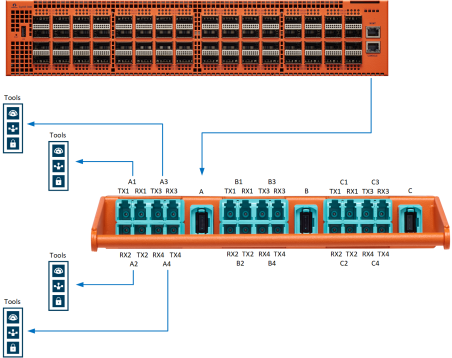
| 1 | PNL-M341 Connections for Breakout |
Refer to 2 PNL-M341 Connected to a TA10 for Aggregationfor an example of using the PNL-M341 breakout panel to aggregate multiple ports to a single tool port.
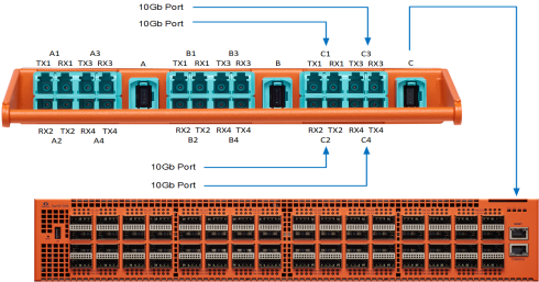
| 2 | PNL-M341 Connected to a TA10 for Aggregation |
MPO and LC Connectors and Cabling
The PNL-M341 breakout panel has three MPO connectors, each going to four LC duplexes. The MPO ports are MTP (UPC with pin-male), aqua color. The LC ports are LC (UPC), aqua color.
The MPO port connectors support 40Gb/100Gb SR4 MM QSFP+/QSFP28 transceivers. The LC port connectors support 10Gb/25Gb SR MM SFP+/SFP28 transceivers.
The MPO port connectors take MM QSFP MTP(F)/UPC-MTP(F)/UPC cabling.
The LC port connectors take MM LC/UPC-LC/UPC duplex cabling.
PNL-M343 Breakout Panel Connection
The PNL-M343 is a Singlemode (SM) breakout panel with a granularity of three breakouts per module. It provides three MPO ports for 40Gb PLR4 optics and twelve LC ports for 10Gb LR optics.
Note: Purchase MPO and LC patch cables separately.
The PNL-M343 breakout panel contains three breakout modules labeled A, B, and C, and can be used for the breakout of a 40Gb port to four 10Gb links or for the aggregation of four 10Gb links to a 40Gb port.
Refer to 3 PNL-M343 Connections for Breakout for an example of using the PNL-M343 breakout panel to breakout a single 40Gb tool port to multiple 10Gb fiber outputs.
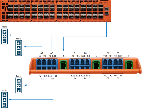
| 3 | PNL-M343 Connections for Breakout |
Refer to 4 PNL-M343 Connected to a TA10 for Aggregation for an example of using the PNL-M343 breakout panel to aggregate multiple ports to a single tool port.
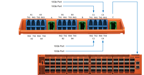
| 4 | PNL-M343 Connected to a TA10 for Aggregation |
MPO and LC Connectors and Cabling
The PNL-M343 breakout panel has three MPO connectors, each going to four LC duplexes. The MPO ports are MTP (APC with pin-male), green color. The LC ports are LC (UPC), blue color.
The MPO port connectors support 40Gb/100Gb PLR4 SM QSFP+ transceivers. The LC port connectors support 10Gb/25Gb LR SM SFP+ transceivers.
The MPO port connectors take SM QSFP MTP(F)/APC-MTP(F)/APC cabling.
The LC port connectors take SM LC/UPC-LC/UPC duplex cabling.
Connecting the PNL-M341 or PNL-M343 for Breakout
To use the PNL-M341 or PNL-M343 to breakout a single port to multiple ports:
| 1. | On the GigaVUE node, set the port mode to 4x for the 40Gb ports that will connect to the breakout panel. You can change the mode using GigaVUE-OS CLI or GigaVUE-FM. |
| 2. | Use a patch cable to connect the GigaVUE node to an MPO port (such as A) on the breakout panel. The traffic on MPO Port A is sent to four different transmitting LC ports, such as TX1 to TX4 on A1 to A4. |
| 3. | Connect the LC ports (such as A1 to A4) on the breakout panel to tools. |
Refer to 1 PNL-M341 Connections for Breakout or 3 PNL-M343 Connections for Breakout.
Connecting the PNL-M341 or PNL-M343 for Aggregation
To use the PNL-M341 or PNL-M343 breakout panel to aggregate multiple GigaVUE 10Gb ports (from a network port or 10Gb tool port) to a single 40Gb fiber output:
| 1. | Connect the GigaVUE 10Gb port to any of the receiving LC ports on the breakout panel, such as Rx1 to RX4 on C1 to C4. These ports are aggregated to the corresponding MPO port (C). |
| 2. | Connect the MPO port (C) on the breakout panel, to the destination 40Gb port. |
Note: If the destination port is a 40Gb network port on a GigaVUE HC Series or GigaVUE TA Series visibility node, the port must be in 4x mode.
Refer to 2 PNL-M341 Connected to a TA10 for Aggregation or 4 PNL-M343 Connected to a TA10 for Aggregation.


