5G-Cloud Ericsson SCP Support
The 5G Core follows a service-based architecture where control plane network functions communicate using the HTTP2 protocol. In Ericsson SCP Mode, HTTP2 transactions are mirrored through the Service Communication Proxy (SCP) and encapsulated using UDP-GRE for further processing.
Ericsson SCP
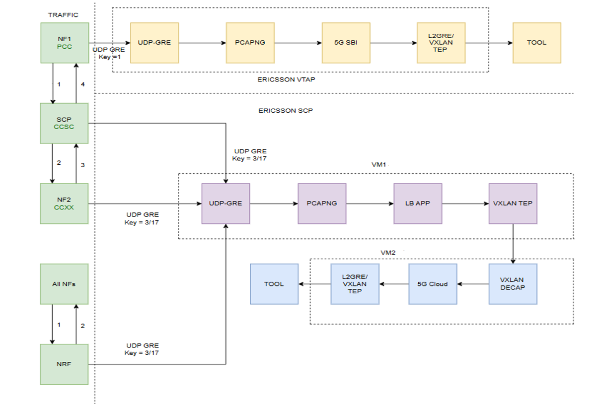
In Ericsson vTAP, traffic is tapped from the Packet Core Controller (PCC), including AMF and SMF, in Layer 7 HTTP SBI JSON format. The 5G SBI application supports this PCC traffic, ensuring efficient processing and monitoring. Refer to 5G-Service Based Interface Application.
In Ericsson SCP mode, the Service Communication Proxy (SCP) mirrors 5G SBI traffic within the Cloud Core Signaling Controller, capturing communication between multiple network functions via SCP.
The 5G-Cloud application in GigaVUE V Series Nodes is enhanced to receive and process traffic from the Ericsson SCP and forward it to the monitoring tools. This setup supports both configuration and visualization through GigaVUE-FM integration.
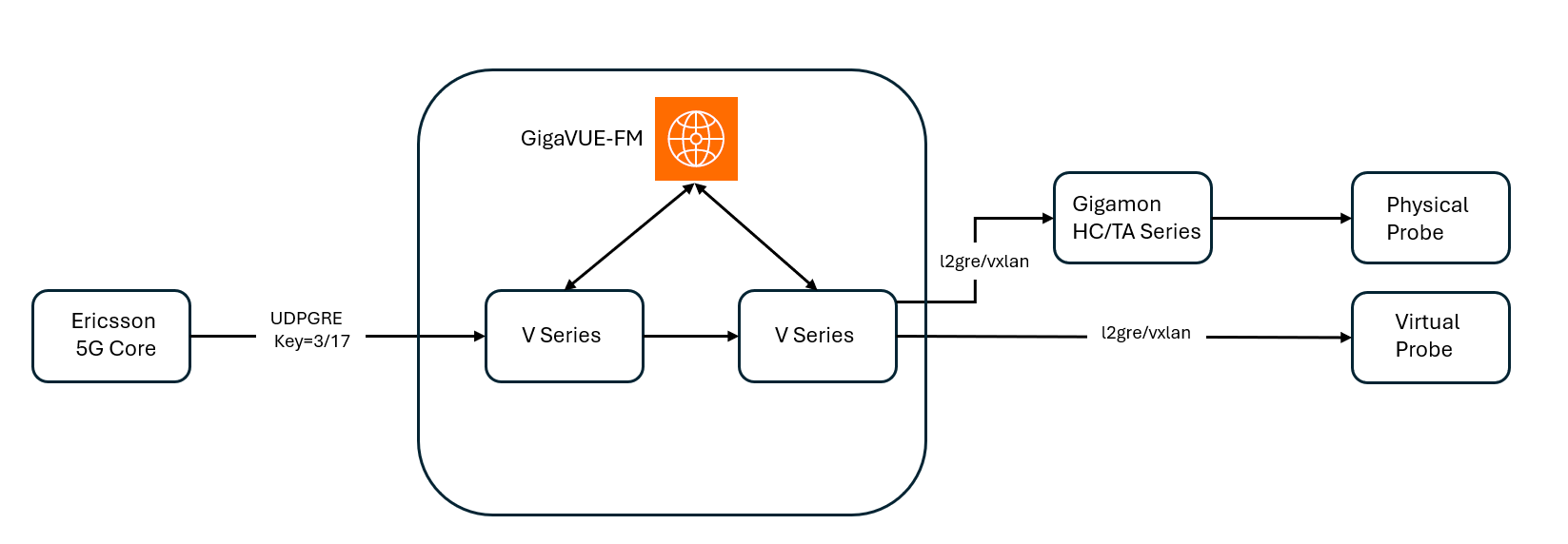
Traffic from the Ericsson 5G Core is encapsulated using UDP-GRE tunnels, with specific keys 3 and 17, to identify different traffic flows from SCP. GigaVUE-FM serves as the centralized management platform orchestrating the visibility fabric, which includes the V Series Nodes. The V Series Nodes inspect, aggregate, and process the incoming packets. After processing, traffic is encapsulated using L2GRE or VXLAN tunneling protocols and forwarded to either physical or virtual probes as follows:
| Physical Probe: If IP connectivity is not available, the traffic is sent to a GigaVUE HC/GigaVUE TA Series device, which serves as a traffic aggregator and distributor. The device decapsulates and distributes the traffic to the probe. |
| Virtual Probe: If IP connectivity is available, the processed traffic is forwarded directly to virtual probe for detailed traffic inspection and analytics. |
This end-to-end solution ensures comprehensive visibility into 5G network traffic, facilitating efficient monitoring and performance analysis across both physical and cloud-based infrastructures.
How Ericsson SCP Solution works
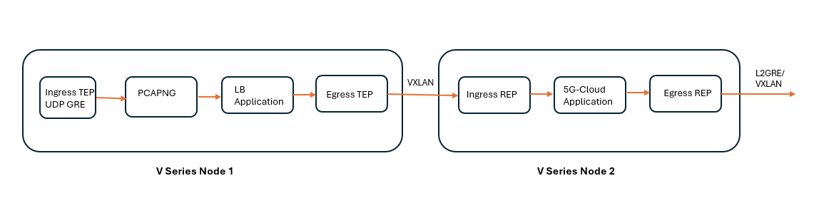
The following figure shows the block diagram of the data flow in the V Series Nodes.
The encapsulated traffic enters the system, and based on the key values, is passed through a PCAP-NG, 5G SBI, and LB application to capture and monitor the data.
For traffic mirroring and flow processing in Ericsson VTap 5G Core network with key value 1, refer to 5G-Service Based Interface Application
When traffic is processed through keys 3 and 17, the PCAPng application reads and validates various blocks within received PCAPng files before forwarding them to the Load Balancing application. It processes data based on the packet type, which includes a combination of the following blocks. Refer to PCAPng Application.
| 1. | Mandatory Blocks: |
| Section Header Block (SHB) |
| 2. | Optional Blocks: |
| Interface Description Block (IDB) |
| Enhanced Packet Block (EPB) |
| Simple Packet Block |
| Name Resolution Block |
| Interface Statistics Block |
The Load Balancing application efficiently distributes traffic with different flow IDs across multiple cores, enabling parallel processing of packets with distinct stream IDs. It ensures that request and response frames with the same stream ID are processed sequentially within the same core, preventing race conditions where these frames might otherwise be handled in parallel across different cores. Refer to Load Balancing.
The extracted data is encapsulated within a VXLAN and routed to the 5G-Cloud application. The 5G-Cloud application processes VXLAN packets by first decapsulating them to extract the HTTP2 headers and body. It then parses the EEVTAP TCP mirrored message and maps the transaction ID to track the full transaction.
After synthesizing the TCP flow and HTTP2 session to represent the complete 5G CNF/SCP/5G CNF transaction data, it forwards the data over an L2GRE/VXLAN tunnel to the probe. Refer to Create Ingress and Egress Tunnels.
| Ericsson SCP will process only Model C traffic. |
| You can deploy traffic ingress applications together in a single V Series Node and Monitoring Session. However, for the 5G-Cloud and egress applications, you must deploy a separate Monitoring Session and V Series Node. |
| You can configure either a single-tep or multi-tep setup for the egress tunnel. Switching between these configurations is not allowed; to make changes, you must undeploy and redeploy the Monitoring Session. |
| Ensure that all V Series Nodes within a single Monitoring Domain are running the same version. Mixing different versions in the same Monitoring Domain may lead to inconsistencies when configuring Monitoring Session traffic elements. |
Configuration of 5G-Cloud Ericsson SCP
In GigaVUE-FM, you must do the following to configure the 5G-Cloud application in the Monitoring Session of a Monitoring Domain in the V Series:
|
S.No |
Steps |
Refer to |
||||||
|
V series Node 1 |
||||||||
|
1 |
Configure UDP-GRE Ingress TEP to receive the HTTP2 messages. Note: You should configure individual UDP-GRE tunnels for each of the following key values:
|
Create Ingress and Egress Tunnel (VMware vCenter) |
||||||
|
2 |
Configure PCAPng application and link ingress TEP and PCAPng application instances in the Monitoring Session. |
|||||||
|
3 |
Configure LB application and link LB application and PCAPng application instances in the Monitoring Session. |
|||||||
|
4 |
Create a VXLAN egress TEP. |
Create Ingress and Egress Tunnel (VMware vCenter) |
||||||
|
5 |
Create a link between egress TEP and LB application. |
|
||||||
|
V series Node 2 |
||||||||
|
6 |
Create a ingress REP to extract the HTTP2 body. |
Create Raw Endpoint (VMware vCenter) |
||||||
|
7 |
Create a link between the VXLAN egress TEP and ingress REP. |
|
||||||
|
8 |
Add the 5G-Cloud application in the Monitoring Session. |
|||||||
|
9 |
Create a link between ingress REP and the 5G-Cloud application. |
|
||||||
|
10 |
Create egress REP. |
Create Raw Endpoint (VMware vCenter) |
||||||
|
11 |
Create a link between the 5G-Cloud application and egress REP. |
|
||||||
Add 5G-Cloud Application in Ericsson SCP
Pre-requisite:
-
You must upload CSV files containing a valid FQDN, NF Instance, and User Agent IDs and a valid IPv4/IPv6 address. Refer to Add CSV file for IP Mapping.
You can add a 5G-Cloud application to:
| New Monitoring Session - Add the 5G-Cloud application after creating a new Monitoring Session and when the GigaVUE-FM canvas appears. Refer to Create a Monitoring Session section in the respective GigaVUE Cloud Suite Deployment Guide. |
| Existing session - Select any existing Monitoring Session and go to TRAFFIC PROCESSING tab. The GigaVUE-FM canvas appears. |
To add a 5G-Cloud application:
| 1. | In the canvas, drag and drop the 5G-Cloud application and select Details. The 5G-Cloud quick view appears. |
| 2. | On the application quick view, enter or select the required information as described in the Reference - Configuration Table. |
Note: It is recommended to maintain a 60-90 second delay when undeploying and deploying a Monitoring Session in GigaVUE-FM.
Reference - Configuration Table
|
Field |
Description |
||||||||||||||||||
|
Application |
The name 5g-Cloud appears by default. |
||||||||||||||||||
|
Alias |
Enter the alias name as cloud5g. |
||||||||||||||||||
|
Mode |
From the drop-down list, select Ericsson SCP Transparent. |
||||||||||||||||||
|
RX Tunnel |
|||||||||||||||||||
|
Type |
Specify the tunnel type. The default is VXLAN. |
||||||||||||||||||
|
Listening IP |
Specify the tunnel's local listen IP address to receive the packet. |
||||||||||||||||||
|
Listening Port |
Specify the tunnel's local listening port to bind to receive the packet. The application will listen to the traffic coming to the specified port. Enter a value between 1 and 65535. |
||||||||||||||||||
|
Source Port |
Specify the tunnel destination port from where the packets will be sent. Enter a value between 1 and 65535. |
||||||||||||||||||
|
VNI Id |
Specify the VNI to use for the VXLAN traffic. Enter a value between 0 and 16777215. The default value is zero. |
||||||||||||||||||
|
RX Thread |
Specify the RX value to receive the packet. Enter a value between 1 and 16. The default value is 8. |
||||||||||||||||||
|
TX Tunnel |
|||||||||||||||||||
|
Type |
Specify the tunnel type. |
||||||||||||||||||
|
Tool IP |
Specify the remote IP address to send the packet. |
||||||||||||||||||
|
Destination Port |
Specify the tunnel destination port to which the packet will be sent. Enter a value between 1 and 65535. |
||||||||||||||||||
|
Source IP |
Specify the source IP address to use when sending the packet. |
||||||||||||||||||
|
Source Port |
Specify the tunnel source port to bind when sending the packet. Enter a value between 1 and 65535. |
||||||||||||||||||
|
VNI Id (Applicable only when the selected tunnel type is VXLAN) |
Specify the VNI to use for the VXLAN traffic. Enter a value between 0 and 16777215. |
||||||||||||||||||
|
L2GRE Key (Applicable only when the selected tunnel type is L2GRE) |
Specify the key for the L2GRE tunnel type. Enter a value between 0 and 4294967295. |
||||||||||||||||||
|
Advanced Setting |
|||||||||||||||||||
|
Tool MTU |
Specify the tool port MTU. |
||||||||||||||||||
|
Log Directory |
Specify the path to store the log files. |
||||||||||||||||||
|
Log Level |
Select the severity log level of the events from the following options:
|
||||||||||||||||||
|
SCP Config |
|||||||||||||||||||
|
FQDN Mapping |
Specify the alias name created for the uploaded FQDN table CSV file. |
||||||||||||||||||
|
NF Instance Mapping |
Specify the alias name created for the uploaded NFID table CSV file. |
||||||||||||||||||
|
User Agent Mapping |
Specify the alias name created for the uploaded User Agent table CSV file. |
||||||||||||||||||
|
TCP Server Ports |
Specify the TCP server port or port range to allow TCP communication endpoints. |
||||||||||||||||||
|
SCP Advanced Config |
|||||||||||||||||||
|
No. of TCP Flows |
Specify the total number of concurrent TCP flows. Enter a value between 128 and 2048. The default value is 1024. |
||||||||||||||||||
|
No. of Transaction Flows |
Specify the total number of Transaction Stream Flows allocated for tracking active Transaction Streams. Enter a value between:
The default value is 2048. |
||||||||||||||||||
|
TCP Flow Timeout |
Specify the TCP flow timeout ranging between 0 to 7200. The default value is 900. |
||||||||||||||||||
|
SCP Transaction Timeout |
Specify the SCP transaction timeout value ranging between 1 and 300. The default value is 10. Note: The recommended timeout value is between 10 and 20 seconds. An increase in the transaction timeout value will impact the total number of transactions that can be processed in parallel. |
||||||||||||||||||
|
Minimum TCP Client Port |
Specify the minimum value to be used for TCP client port ranging between 1023 and 65535. The default value is 32768. |
||||||||||||||||||
|
Maximum TCP Client Port |
Specify the maximum value to be used for client port ranging between 1023 and 65535. The default value is 36863. |
||||||||||||||||||
|
SCP Processing Threads |
Specify the number of worker threads for processing In-Out packets. Enter a value between 1 and 16. The default value is 8. |
||||||||||||||||||
|
TCP Client Ports per Thread |
Specify the number of TCP client ports for each worker thread. Enter a value between 100 and 8000. The default value is 1000. |
||||||||||||||||||
|
Header Index |
Enable or disable the header indexing. The default value is disabled. |
||||||||||||||||||
|
Header Compression Code |
Enable or disable the header compression code. The default value is disable. |
||||||||||||||||||
|
Gigamon Header |
Enable or disable the Gigamon Header. The default value is Enable. |
||||||||||||||||||
|
Packet Capture Level |
Select the packet capture level from the drop-down list:
|
||||||||||||||||||
|
5G-Cloud Log Level |
Select the required 5G-Cloud CSV log level from the drop down list. The default value is None.
|
||||||||||||||||||
|
HTTP2 Monitored Flows |
|||||||||||||||||||
|
Number of Streams |
Specify the number of monitored stream flows. Enter a value between 1024 and 16384. The default is 1024. |
||||||||||||||||||
|
Request Timeout |
Specify the HTTP/2 request timeout in seconds. Enter a value between 1 and 300. The default is 15 seconds. |
||||||||||||||||||
|
Response Timeout |
Specify the HTTP/2 response timeout in seconds. Enter a value between 1 and 300. The default is 2 seconds. |
||||||||||||||||||
|
TCP Monitored Flows |
|||||||||||||||||||
|
Number of Flows |
Specify the number of monitored TCP flows. Enter a value between:
The default value is 2048. |
||||||||||||||||||
|
Flow Timeout |
Specify the timeout for TCP flows in seconds. Enter a value between 1 and 7200. The default value is 60 seconds. |
||||||||||||||||||
|
Flow Reassembly Timeout |
Specify the timeout for TCP flow reassembly in seconds. Enter a value between 1 and 7200. The default value is 500 seconds. |
||||||||||||||||||
Download Logs - 5G-Cloud application
You can view the log files of a V Series Node or download them as .CSV or .txt files.
To download the log files to a local environment:
| 1. | Go to Traffic > VIRTUAL > select your cloud platform. |
| 2. | Select the required Monitoring Session and click Details on the 5G-Cloud application. Go to LOGGING in the quick view. The Logging page displays the logs currently available. |
| 3. | Select the required Days, Timestamps, File Name, and Type (TextLog and FlowStats) details. |
| 4. | Select the log files to download, and then click Download > Files. The system downloads the selected files to your local environment. |
Add CSV file for IP Mapping
To add the CSV file for IP mapping:
| 1. | Go to Inventory > VIRTUAL > select your cloud platform, and then click Settings > 5G-Apps. The 5G-Apps Configuration page appears. |
| 2. | Click New. Enter the name for the CSV file in the Alias field |
| 3. | From the Type drop-down list, select one of the following: |
| 5G-Cloud FQDN - Add the CSV file containing a valid FQDN ID and a valid IPv4/IPv6 address for IP mapping. |
| 5G-Cloud NF Instance - Add the CSV file containing a valid NF instance ID and a valid IPv4/IPv6 address for IP mapping. |
| 5G-Cloud UA - Add the CSV file containing a valid user agent ID and a valid IPv4/IPv6 address for IP mapping. |
| 4. | Click Choose File in the FileName field to upload the CSV file into GigaVUE-FM. |
| FQDN Mapping: gigamon@vseries:/var/log/cloud5g_tabledir$ cat FQDN.txt |
| Header details: FQDNid,IngressIP1,IngressIP2,IngressPort,EgressIP,NFType,NFLocation |
| Example: s25scp01.scp.5gc.mnc003.mcc525.3gppnetwork.org,170.00.13.187,,8080,,SCP,plolp |
| NF Instance Mapping: gigamon@vseries:/var/log/cloud5g_tabledir$ pwd NFID.txt |
| Header details: NFID,IngressIP1,IngressIP2,IngressPort,EgressIP,NFType,NFLocation |
| Example: 8b94c7xx-d700-4xcd-90be-634x11a5xx0d,100.23.14.4,,8080,,AMF,plolp |
| User Agent Mapping: gigamon@vseries:/var/log/cloud5g_tabledir$ pwd UA.txt |
| Header details: UserAgent,IngressIP1,NFType,NFLocation |
| Example: xx5gs20015gcay01,192.64.10.67,AMF,plolp |
| 5. | Click Validate to validate the CSV file. |
| 6. | Click Save to add the CSV file. |
FHA Dashboards for 5G-Cloud Applications
After configuring the 5G-Cloud application, you can monitor the statistics for Ericsson SCP by the reports displayed in the Dashboard. To access the details, refer to FHA Dashboards for 5G-Cloud Applications.


