GigaSMART NetFlow Generation
Required License: NetFlow Generation
Required License for NetFlow with Second Level Maps: Adaptive Packet Filtering (APF)
NetFlow Generation is a simple and effective way to increase visibility into traffic flows and usage patterns across systems. The flow-generated data can be used to build relationships and usage patterns between nodes on the network. Routers and switches that support NetFlow can collect IP traffic statistics to be exported as NetFlow records.
However, the processor and memory load of enabling NetFlow can cause service degradation and affect their ability to pass traffic without introducing latency and packet drops. Due to this processing overhead, sampled NetFlow is implemented in most of the high-end routers. Sampling in every “N” packets for NetFlow processing can severely limit the visibility needed to monitor flows.
The advanced capabilities of GigaSMART® technology can be leveraged to summarize and generate unsampled NetFlow statistics from incoming traffic streams. Offloading NetFlow Generation to an out-of-band solution like the Gigamon Visibility Platform completely eliminates the risk of using core production network resources in generating this data. Combined with the flexibility offered by Gigamon’s patented Flow Mapping® technology, operators can pick and choose from which flows to generate NetFlow statistics, while at the same time sending the original packets to other monitoring tools.
Support for NetFlow versions 5 and 9 and IP Information Export (IPFIX), as well as CEF, enables seamless integration with standards-based collectors. NetFlow records can also be exported to multiple collectors concurrently, providing a single flow source for business-critical management applications such as security, billing, and capacity planning. Exported flows can also be filtered so that collectors only receive the specific records relevant to them.
Gigamon has also extended IPFIX to include URL information, providing insight into HTTP and SIP traffic. Other enterprise extensions for IPFIX are HTTP, DNS, and SSL certificates, which provide metadata that can be used for security analysis.
Additionally, Gigamon’s Visibility Platform architecture is the first in the industry to summarize flow statistics as well as to provide the flexibility of aggregating, replicating, filtering, and forwarding raw traffic streams to monitoring tools for detailed troubleshooting and analytics.
The Gigamon Visibility Platform establishes a scalable framework to deliver pervasive flow-level visibility across enterprises, data centers, and service provider environments to accurately design, engineer, optimize, and manage their network infrastructure.
Note: NetFlow Generation exports records using IPv4. IPv6 is not supported.
GigaSMART operations with a NetFlow component can be assigned to multiple GigaSMART groups or GigaSMART groups consisting of multiple GigaSMART engine ports.
NetFlow/IPFIX Generation is a pillar of the GigaSECURE Security Delivery Platform.
NetFlow Generation is displayed in Figure 857: NetFlow Generation Gigamon Solution.
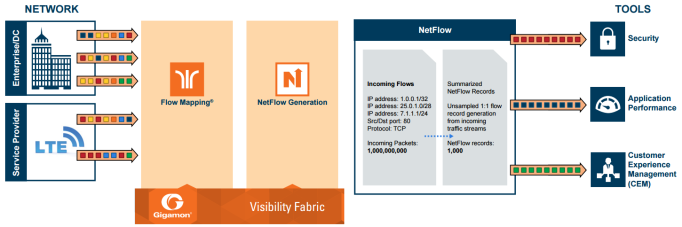
Figure 857: NetFlow Generation Gigamon Solution
In Figure 857: NetFlow Generation Gigamon Solution, incoming packets from network(s) enter the Gigamon Visibility Platform and are directed by maps to NetFlow. NetFlow examines the incoming packets and converts the packets of choice into flows records. Specific flows are then forwarded to specific tools, such as Security, Application Performance, and Customer Experience Management (CEM) tools.
NetFlow Generation Components
NetFlow Generation collects IP traffic statistics on all interfaces where a NetFlow Monitor is enabled. It then gathers the statistics of the traffic flows and exports the NetFlow records to at least one NetFlow collector (typically a device that performs the actual traffic analysis based on the information from the NetFlow records).
Figure 858: NetFlow Generation Components shows the NetFlow Generation components.
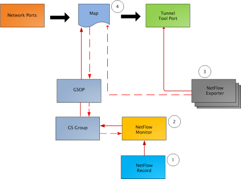
Figure 858: NetFlow Generation Components
illustrates the NetFlow Generation and how its components are associated. The NetFlow Generation associates its components in the following order:
| 1. | One or more Records are associated to the Monitor. |
| 2. | The Monitor is associated to the GigaSMART group. |
| 3. | The Exporter is associated to the IP interface with tool port. |
| 4. | The map will eventually bind to the Exporter, Record, and Monitor. |
Note: The dotted line from the map represents the interaction between the NetFlow Generation components.
Refer to Example 1: NetFlow Generation Configuration on page 631 for an example configuration of the following components.
Network Ports
NetFlow operates on the network flow. The incoming traffic on the network ports contains inputs such as, source and destination IP addresses, source and destination ports, interfaces, and so on. The network ports provide traffic to maps.
Map(s)
Traffic is received and acted upon according to maps. Maps determine what traffic is forwarded to NetFlow. Through map configuration, you add rules to filter the packets that need to go to NetFlow, and associate the map to the IP interface with tool port to specify where to send the filtered traffic.
Starting in software version 4.3.01, NetFlow supports both first level and second level maps. First level maps contain flow mapping rules to filter traffic that is needed by NetFlow and then send the filtered traffic to the IP interface with tool ports.
Second level maps are used for configuring filtering rules enabled through Adaptive Packet Filtering (APF). A virtual port is configured that directs traffic to the second level map. After the APF rules are applied, the filtered traffic that is needed by NetFlow is sent to the IP interface tool ports.
For examples of first level maps, refer to Example 1: NetFlow Generation Configuration and Example 2: NetFlow Generation Configuration.
For examples of first and second level maps, refer to Example 3: NetFlow Generation Configuration and Example 4: NetFlow Generation Configuration.
GigaSMART Group
The GigaSMART group specifies the GigaSMART engine to use, such as 8/1/e1 or
8/1/e2.
GSOP
The GigaSMART operation enables NetFlow. If a second level map is configured, the GigaSMART operation directs traffic to APF first, and then to NetFlow.
NetFlow Records
A NetFlow record contains key elements that specify what to match in the flow, such as all packets with the same source and destination port, or anything that comes in on a particular interface. A flow record also contains non-key elements that specify what information to collect for the flow, such as when the flow started or the number of bytes in the flow.
For NetFlow-v5, the fields in the flow record are fixed. For details, refer to V5 Fixed Record Template on page 657.
For NetFlow-v9 and IPFIX, you configure the fields, and thus create a record template. You specify how the fields are organized and in what order. The template is sent to the collector, so the collector knows what fields to expect in a NetFlow record. The template is sent periodically.
Starting in software version 4.6, multiple records are supported. An increased number of records allows more NetFlow data to be exported.
The maximum number of records is five. For all five records, each record must have the same match fields but differing collect fields. The same match fields will define the flows being considered. The different collect fields will define multiple templates sent to the NetFlow servers.
Starting in software version 5.1 for IPFIX and software version 5.2 for v5 and v9, a mix of IPv4 and IPv6 collect fields (IPv4 source/destination and IPv6 source/destination) are not supported in one record. Instead, create two records, one for IPv4 collect fields and one for IPv6 collect fields. When the IPv4/IPv6 collect fields are in separate records, an exporter will only send out records with non-blank elements.
NetFlow Monitors
Monitors store the NetFlow records associated with them. The configuration of a monitor includes the definition of the cache that specifies the records that you want to store, as well as timeouts associated with the cache. The cache can contain up to 4 million entries.
There can be a maximum of two monitors on a GigaSMART line card or module, one associated with each e port.
Starting in software version 4.6, up to five records can be added to the monitor. This results in the creation of five templates. For all five records, each record must have the same match fields but differing collect fields.
Sampled NetFlow Data
NetFlow data can be sampled. Sampling reduces the amount of ingress traffic sent to NetFlow for processing, which reduces the load on external collectors.
A NetFlow monitor can have multiple records with different sampling rates. The records are only updated with packets at the rate specified.
The following types of sampling are available: single-rate or multi-rate, as well as no sampling.
Sampling is enabled and disabled on the NetFlow monitor, across all flows. When sampling is enabled, you define the sampling rate by specifying a number for 1 in N, where N is the packet count.
For single-rate, the number can be from 10 to 16000. For multi-rate, the number can be from 1 to 16000. Single-rate applies to all records, whereas multi-rate applies to any record.
For example, if sampling is 1 in 1024, 1 packet in 1024 will be selected for NetFlow. The default is 1 in 1, which means no sampling.
Note: The sampling mode in this release is deterministic. The selection of the packet is not random. Deterministic sampling means that if the rate is 1 in 1024, after 1023 packets, the 1024th packet is selected, while packets 1 to 1023 are ignored.
NetFlow Exporters
NetFlow records are sent to exporters. Each exporter is associated with one external collector. There can be up to six exporters that send flow records to up to six external collectors. The six destinations are per GigaSMART engine.
The configuration of an exporter includes the IP address of a collector, the transport protocol and destination port, and the template refresh interval, which specifies the frequency of when the record template is sent to the collector.
Starting in software version 5.1, an option is added to assign different exporters to different records. Instead of records being sent to all exporters, you can add an exporter to a record, which defines the exporter to which the record is sent.
IP Interface with Tool Ports
NetFlow exporters are associated with IP interface, since exporters route both records and templates to collectors in the network.
Note: It is expected that the gateway specified in the IP interface configuration does Layer 3 routing. However, when the tIP interface and the collector’s IP address are in the same subnet, the following applies:
| • | Configure the IP interface’s gateway IP address to the same as the collector’s IP address. |
| • | Configure the IP interface’s subnet mask to 255.255.255.255. |
| • | The maximum number of exporters supported by the IP interface is one. |
Enhancements to NetFlow
In addition to the NetFlow components, there are also the following enhancements:
| • | Exporter Filtering |
| • | Remote Interface IDs |
| • | NetFlow Option Templates |
| • | IPFIX Extension: HTTP Response Code |
| • | IPFIX Extension: Packet URL |
| • | IPFIX Extension: User Agent |
| • | IPFIX Extension: Domain Name Service (DNS) |
| • | IPFIX Extension: SSL Metadata |
| • | SNMP Packet Support on IP Interfaces with Tool Ports |
| • | NetFlow Format Support on Exporters |
Exporter Filtering
Not all collectors are interested in all kinds of packets. On each exporter, you can configure pass filters to filter the records transmitted to a collector. Thus, you can send a subset of records to a collector, such as the flow records for UDP packets or for packets coming in on a particular port.
Filtering is based on criteria, such as ports or IP addresses. For example, you can filter on different interfaces, such as single port (1/1/x1) or a contiguous range of ports (1/1/x1..x4). Note that you can only filter the criteria or a subset of the criteria that you configured for the match fields in the record.
Note: If no filters are configured, all records are sent to the collectors.
The exporter pass filters are as follows:
| • | Input interface |
| • | IPv4 and IPv6 DiffServ Code Point (DSCP) |
| • | IPv4 and IPv6 source address |
| • | IPv4 and IPv6 destination address |
| • | IPv4 protocol |
| • | IPv4 Type of Service (TOS) |
| • | IPv6 flow label |
| • | L4 source and destination port |
| • | MAC source and destination address |
| • | VLAN ID |
Take into account the following considerations:
| • | an exporter can have up to 5 filter rules |
| • | each rule can have up to 4 attributes |
| • | input interface can only be specified once per filter |
| • | other attributes can be specified multiple time in a rule |
| • | two rules cannot be identical |
For an example of exporter filtering, refer to Example 2: NetFlow Generation Configuration.
Remote Interface IDs
Interface ID, ingress as well as egress, can be configured as match and collect fields. Interface IDs can be local or remote. If you are interested in the interface ID on which a packet arrives, you need the port number of the node sending the packet. To get that information, you can use the LLDP/CDP discovery protocols that talk to neighbors to fetch the remote interface ID.
Discovery has to be either enabled or disabled on all the ports in a map. If discovery is enabled, the remote interface ID is sent in the NetFlow data record, as learned through LLDP/CDP.
To configure port discovery with NetFlow, enable discovery on the port or ports that are specified in the Source field of the associated map.
Note the following:
| • | You cannot modify discovery once the map is defined. |
| • | Local port IDs are unique across a cluster. Remote IDs might not be unique. With port discovery enabled, there is a possibility of port ID collisions. |
Note: If port discovery is not enabled, the local port ID is sent in the NetFlow data record.
When port discovery is enabled, the sending of the remote ID requires the collaboration of the end nodes. NetFlow expects an integer for port ID. If end nodes send an alphanumeric string, MAC address, or IP address (non-integers), that cannot be translated in an integer, NetFlow interprets them as either 0xFFFF or 0xFFFFFFFF.
When port discovery is enabled and ingress LLDP/CDP packets contain interface IDs that cannot be translated into an integer, use the collect field interface input name in the flow record definition. Using an interface name will send meaningful information about a network port to help identify the port to which the flow record refers.
To use the collect field interface input name, do the following:
| 1. | From the device view, select GigaSMART > NetFlow / IPFIX Generation > Records. |
| 2. | Click New to create a new Record or select the recored and click Edit to change an existing record. |
| 3. | Click in the field Non-Key Fields (Collect) and select Interface from the list. |
| 4. | Select Input and then Input Name. Specify an input Width as shown in Figure 859: Collect Field Interface input Name. |
| 5. | Click Save. |
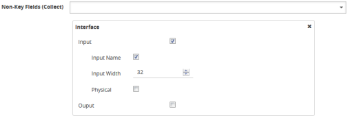
Figure 859: Collect Field Interface input Name
NetFlow Option Templates
For NetFlow-v9 and IPFIX, each exporter periodically sends option templates and option data records. There are two supported option templates, as follows:
| • | Interface ID to name mapping template and data record |
| • | Exporter statistics template and data record |
The option template for interface ID to name mapping contains an interface ID and name pair. Instead of a local port ID, the actual port number is available. For NetFlow-v9, the name field has a fixed length of 32 bytes. Names shorter than 32 bytes will be padded, while names longer than 32 bytes will be truncated. For IPFIX, the name field is of variable length.
Note: When port discovery is disabled for the port or ports specified in the Source field of the associated map, the interface option data record sends the interface ID to name mapping. But when discovery is enabled, interface option data records are not sent.
Each exporter sends out statistics, based on the standards. The exporter statistics option template includes information such as the exported flow record count, the exported message total count, and the exported octet total count.
By default, the transmission of option templates from the exporter is always enabled. The frequency of the transmission can be configured using the Template Refresh interval field in the NetFlow Exporter configuration page. To open the configuration page, select GigaSMART > NetFlow / IPFIX Generation > Exporters and click New.
IPFIX Extension: HTTP Response Code
For IPFIX only, use the collect field Private PEN HTTP Response Code in the flow record definition for capturing any packet with an HTTP response code embedded in it. This is a private information element extension, specific to Gigamon. The only valid private enterprise name (pen) is gigamon.
The HTTP response code information is captured from the packet and reported in the NetFlow record. The captured HTTP response code will be from the first packet that has HTTP/1 at the start of the HTTP header.
The field length in the flow record is a fixed length of 2 bytes.The range of response code values is from 100 to 599, as follows:
| • | 100-199 (informational) |
| • | 200-299 (success related) |
| • | 300-399 (redirection) |
| • | 400-499 (client requests) |
| • | 500-599 (server related) |
If there is no HTTP response code in the flow, a zero value will be reported.
Note: In releases prior to software version 5.2, HTTP Response Code was directly under Private PEN. Starting in software version 5.2, there is a new HTTP section with Response Code under it. For backwards compatibility, both are supported.
To configure the NetFlow record for capturing any packet with an HTTP response code embedded in it, do the following:
| 1. | From the device view, select GigaSMART > NetFlow / IPFIX Generation > Records. |
| 2. | Click New. Refer to Figure 860: NetFlow Record Configuration for HTTP Response Code. |
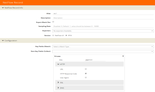
Figure 860: NetFlow Record Configuration for HTTP Response Code
| 3. | For Version, select IPFIX. |
| 4. | Click the Non-Key Fields (Collect) drop-down list and select Private. |
| 5. | In the Private non-key field, do the following: |
| • | Set PEN to gigamon. (This is the default.) |
| • | Select HTTP Response Code. |
| 6. | Click Save. |
IPFIX Extension: Packet URL
For IPFIX only, use the collect field Private PEN HTTP URL in the flow record definition for capturing any packet with a URL embedded in it. This is a private information element extension, specific to Gigamon. The only valid private enterprise name (pen) is gigamon.
The following URL information is captured from the packet and reported in the NetFlow record:
| • | HTTP: GET, POST, PUT, DELETE, and HEAD method types |
| • | SIP: INVITE, ACK, BYE, REGISTER, OPTIONS, and CANCEL request types |
The captured URL will be from the first packet that contains a URL. If there are additional URLs in subsequent packets in the flow, they will be ignored. If there is no URL in the flow, a zero length will be reported.
Note: The URL will always appear as the last element in a template, no matter the order in which the collect fields were configured.
Note: In releases prior to software version 5.2, URL was directly under Private PEN. Starting in software version 5.2, there is a new HTTP section with URL under it. For backwards compatibility, both are supported.
In Figure 860: NetFlow Record Configuration for HTTP Response Code in the Private non-key field, select URL and enter an optional width.
IPFIX Extension: User Agent
For IPFIX only, use the collect field Private PEN HTTP User Agent in the flow record definition for capturing any packet with a user agent in the HTTP request header to gather information about clients user agents.
In general, the HTTP request is sent from the browser to the web application, so User Agent is filled in by the browser. As such, different browsers fill in this field with different values.
The maximum user agent length that is allowed in the data record is 250 bytes. The default is 150 bytes. Use the width parameter to specify a user agent length of up to 250 bytes.
In Figure 860: NetFlow Record Configuration for HTTP Response Code in the Private non-key field, select User Agent and enter an optional width.
IPFIX Extension: Domain Name Service (DNS)
For IPFIX only, use the non-key or collect field Private PEN DNS in the flow record definition for capturing any packet with Domain Name Service (DNS) parameters embedded in it. This is a private information element, specific to Gigamon. The only valid private enterprise name (pen) is gigamon.
A domain name service translates host names into IP addresses. DNS has been exploited by attackers. Use this NetFlow enterprise element to gather metadata to help protect against security threats.
When certain DNS parameters are configured, the corresponding values for those collect parameters can be displayed in hexadecimal format or in text format. The following DNS parameters can display their values as text when the text version of that parameter is used:
| • | Additional Class, Additional Class Text |
| • | Additional Type, Additional Type Text |
| • | Authority Class, Authority Class Text |
| • | Authority Type, Authority Type Text |
| • | Query Class, Query Class Text |
| • | Query Type, Query Type Text |
| • | Response Class, Response Class Text |
| • | Response IPv4 Address, Response IPv4 Address Text |
| • | Response IPv6 Address, Response IPv6 Address Text |
| • | Response Type. Response Type Text |
For example, if the DNS query-type parameter collects a hexadecimal value of 0x1, the query-type-text parameter collects the text string A, which refers to the IP address of the host.
The DNS parameters are captured from the packet and reported in the NetFlow record. Refer to Displaying Exporter Statistics and NetFlow Exporter Statistics Definitions.
Handling Blank Records for IPFIX
In the NetFlow record, the collect fields may contain one the following:
| • | Only private enterprise elements such as SSL, HTTP, or DNS |
| • | Only non-private enterprise elements such as source IP address |
| • | Both private and non-private elements |
If all the collect fields contain only the private enterprise elements, and if during run-time, the records are blank or empty, they will not be added to NetFlow, however they will be counted in the exporter statistics as Empty Records Not Added.
If the collect fields contain both private and non-private enterprise elements, and if during run-time, the private enterprise elements are blank or empty, the records can be exported to the collector.
Configuring a DNS Record for IPFIX
To configure the NetFlow record for capturing any packet with (DNS) parameters embedded in it, do the following:
| 1. | Go to GigaSMART > NetFlow / IPFIX Generation > Records. |
| 2. | Click New. Refer to Figure 861: NetFlow Record Configuration for DNS. |
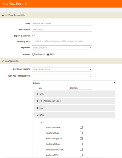
Figure 861: NetFlow Record Configuration for DNS
| 3. | In the Alias field, enter a name. |
| 4. | To export the blank pen records, select Export Blank Pen. |
| 5. | For Version, select IPFIX. |
| 6. | Click the Non-Key fields (Collect) drop-down list and select Private. |
| 7. | In the PEN field, enter gigamon. (This is the default.) |
| 8. | Click DNS and select the parameters. The Number of Collects field is displayed for some DNS parameters. Refer to Table 2: DNS Parameters . |
1In the Number of Collects field, specify the number of instances of elements to collect from the DNS request. The value ranges from 1 to 10. The default value is 1.
| 9. | Click Save. |
|
Method |
For more information: |
|
Additional Name |
The domain name in the additional records section. |
|
Additional Type |
The additional type containing one of the RR type code. |
|
Additional Type Text |
The text string that corresponds to the hexadecimal value of the additional type containing one of the RR type code. |
|
Additional Class |
The additional class containing one of the RR class code. |
|
Additional Class Text |
The text string that corresponds to the hexadecimal value of the additional class containing one of the RR class code. |
|
Additional TTL |
The time-to-live (TTL), which is the time interval in seconds that the record is cached in the additional records section. |
|
Additional RData |
The content that describes the resource in the additional records section. |
|
Additional RData Length |
The length of the rdata field in the additional records section. |
|
AN Count |
The number of resource records in the answer section. |
|
AR Count |
The number of resource records in the additional records section. |
|
Authority Name |
The domain name in the authority section. |
|
Authority Type |
The authority type containing one of the RR type code. |
|
Authority Type Text |
The text string that corresponds to the hexadecimal value of the authority type containing one of the RR type code. |
|
Authority Class |
The authority class containing one of the RR class code. |
|
Authority Class Text |
The text string that corresponds to the hexadecimal value of the authority class containing one of the RR class code. |
|
Authority TTL |
The time-to-live (TTL), which is the time interval in seconds that the record is cached in the authority section. |
|
Authority RData |
The content that describes the resource in the authority section. The format of the rdata field varies according to the type and class of the resource record. |
|
Authority RData Length |
The length of the rdata field in the authority section. |
|
Bits Count |
The variable length of a bit map. The bit map must be a multiple of 8 bits long. For example: "/QR=1/AA=0/TC=0/RD=1/RA=1/AD=0/CD=0/Z=0", where /QR is the query (0) or a response (1), /AA is the authoritative answer, /TC is the truncation, /RD is the recursion desired, /RA is the recursion available, /AD is the authentic data, /CD is the checking disabled, and /Z is the reserved for future use. |
|
Identifier |
The identifier generated by the device that creates the DNS query and is copied by the server into the response so it can be used by that device to match that query to the corresponding reply received from the DNS server. |
|
NS Count |
The number of the name server (NS) resource records in the authority records section. |
|
Op Code |
The query type. |
|
Qd Count |
The number of entries in the question section. |
|
Query Class |
The query format containing one of the RR class codes. |
|
Query Class Text |
The text string that corresponds to the hexadecimal value of the query format containing one of the RR class codes. |
|
Query Name |
The domain name requested in the query. The maximum name length is 64 bytes. If the name is longer, it will be truncated. |
|
Query Type |
The query format containing one of the RR type codes. |
|
Query Type Text |
The text string that corresponds to the hexadecimal value of the query format containing one of the RR type codes. |
|
Response Code |
The type of the response. |
|
Response Class |
The response format containing one of the RR class codes. |
|
Response Class Text |
The text string that corresponds to the hexadecimal value of the response format containing one of the RR class codes. |
|
Response Name |
The domain name in the response. The maximum name length is 64 bytes. If the name is longer, it will be truncated. |
|
Response Type |
The query type specified in the response. |
|
Response Type Text |
The text string that corresponds to the hexadecimal value of the query type specified in the response. |
|
Response RData Length |
The length of the rdata field in the response data field. |
|
Response RData |
The content that describes the resource in the response data field. The format of the rdata field varies according to the type and class of the resource record. |
|
Response-TTL |
The time-to-live (TTL), which is the time interval in seconds that the record is cached. |
|
Response iPv4 Address |
The IPv4 address in the response if the response type host and class are Internet/IPv4. |
|
Response iPv4 Address Text |
The text string that corresponds to the hexadecimal value of the IPv4 address in the response if the response type host and class are Internet/IPv4. The format is dotted decimal. |
|
Response IPv6 Address |
The IPv6 address in the response if the response type host and class are Internet/IPv6. |
|
Response iPv6 Address Text |
The text string that corresponds to the hexadecimal value of the IPv6 address in the response if the response type host and class are Internet/IPv6. The format is dotted decimal. |
IPFIX Extension: SSL Metadata
For IPFIX only, use the collect field Private PEN ssl in the flow record definition for capturing any packet with Secure Sockets Layer (SSL) or server metadata embedded in it, such as common name. This is a private information element extension, specific to Gigamon. The only valid private enterprise name (pen) is gigamon.
Examining the parameters associated with the SSL certificate or the SSL server provides visibility into SSL flows in the network and helps detect malicious activity. For example, checking the issuer might reveal an unknown self-signed certificate or a certificate signed by a questionable Certificate Authority (CA). Checking the certificate validity dates might reveal an expired certificate.
When NetFlow collects SSL certificate metadata, it makes use of the GigaSMART SSL application, described in GigaSMART Out-of-Band SSL Decryption. The data is routed to the SSL application first and then to NetFlow. If de-duplication is also enabled, the data is routed from de-duplication to SSL, and then to NetFlow. The SSL application does not decrypt the data.
Note: Only the NetFlow Generation license is needed for NetFlow to collect SSL certificate metadata.
When certain SSL certificate parameters are configured, the corresponding values for those collect parameters can be displayed in hexadecimal format or in text format. The following SSL certificate parameters can display their values as text when the text version of that parameter is used:
| • | Serial Number, Serial Number Text |
| • | Signature Algorithm, Signature Algorithm Text |
| • | Subject Algorithm, Subject Algorithm Text |
| • | Valid Not After, Valid Not After Text |
| • | Valid Not Before, Valid Not Before Text |
To configure a record for SSL Certificate or SSL Server, do the following:
1From the device view, select GigaSMART > NetFlow / IPFIX Generation > Records.
| 10. | Click New. |
| 11. | For Version, select IPFIX. |
| 12. | Click in the Non-Key fields (Collect) field. |
| 13. | Select Private from the drop-down list. |
| 14. | In the Private non-key field, do the following: |
| • | Set PEN to gigamon. |
| • | Under SSL, select the SSL Certificate and SSL Server parameters and specify a width value in bytes. For example, Certificate Issuer Common Name and Certificate Subject Common Name as shown in Figure 862: NetFlow Record Configuration for SSL. |
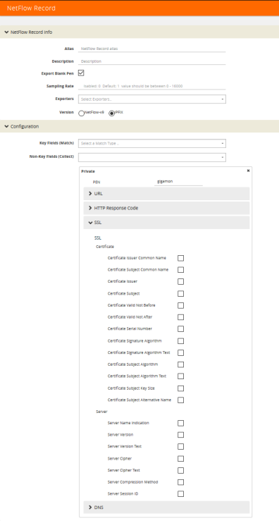
Figure 862: NetFlow Record Configuration for SSL
SSL Certificate Parameters
When certain SSL server parameters are configured, the corresponding values for those collect parameters can be displayed in hexadecimal format or in text format. The following SSL server parameters can display their values as text when the text version of that parameter is used:
| • | Cipher, Cipher Text |
| • | Version, Version Text |
For example, if the ssl server cipher parameter collects a hexadecimal value of C027, the ssl server cipher-text parameter collects the following text string:
TLS_ECDH_RSA_WITH_AES_128_GCM_SHA256
The parameters supported for the SSL certificate are as follows:
| • | Certificate Issuer—the certificate issuer, which identifies the entity that has signed and issued the certificate. For example: "/C=US/ST=Arizona/L=Scottsdale/O=MyCo2.com, Inc./OU=http://certs.myco2.com/repository//CN=MyCo2 Secure Certificate Authority", where /C is the country name, /ST is the state or province, /L is the locality name, /O is the organization name, /OU is the organizational unit name, and /CN is the common name. |
| • | Certificate Issuer Common Name—the certificate issuer common name, which is a subset of Issuer. |
| • | Certificate Subject—the certificate subject, which identifies the entity associated with the public key stored in the subject public key. The Certificate Subject has the same fields as the Certificate Issuer. |
| • | Certificate Subject Common Name—the certificate subject common name, which is a subset of Subject. |
| • | Certificate Subject Alternative Name—the subject alternative name, which allows identities to be bound to the subject of the certificate. This parameter is useful to detect if the certificate claims to sign for anything else and to detect anomalies such as certificates that claim to sign for a wildcard (*). The first subject alternative name present in the certificate is collected. |
| • | Certificate Valid Not Before and Certificate Valid Not After—the date on which the certificate validity period begins and ends. The certificate validity period is the time interval during which the CA warrants that it will maintain information about the status of the certificate. It is expressed in universal time. The format is YYMMDDHHMMSSZ, where Z is Zulu time (GMT). |
| • | Certificate Valid Not Before Text and Certificate Valid Not After Text—the text string that corresponds to the hexadecimal value of the date on which the certificate validity period begins and ends. The format is MMM DD HH:MM:SS YYYY GMT. |
| • | Certificate Serial Number—the unique number for each certificate issued by a given CA. The issuer name and serial number identify a unique certificate. This parameter is useful to detect any certificate changes or substitutions. |
| • | Certificate Serial Number Text—the text string that corresponds to the hexadecimal value of the unique number for each certificate issued by a given CA. |
| • | Certificate Signature Algorithm—the identifier for the cryptographic algorithm used by the CA to sign the certificate, defined in ASN.1 format. This parameter is useful to detect servers that are not compliant with an organization’s cryptographic standards. |
| • | Certificate Signature Algorithm Text—the text string that corresponds to the hexadecimal value of the identifier for the cryptographic algorithm used by the CA to sign the certificate, defined in ASN.1 format. This parameter is useful to detect servers that are not compliant with an organization’s cryptographic standards. |
| • | Certificate Subject Algorithm—the subject public key algorithm used, defined in ASN.1 format, such as RSA or DSA. |
| • | Certificate Subject Algorithm Text—The text string that corresponds to the hexadecimal value of the subject public key algorithm used, defined in ASN.1 format, such as RSA or DSA. |
| • | Certificate Subject Key Size—the subject public key size. |
Optionally, on the issuer, Certificate Issuer Common Name, Certificate Subject, Certificate Subject Common Name, and Certificate Subject Alternative Name parameters, you can indicate the width of the field in bytes.
SSL Server Parameters
The parameters supported for the SSL server are as follows:
| • | Server Name Indication—the extension to the Transport Layer Security (TLS) protocol by which a client indicates the host name to which it is attempting to connect at the start of the handshaking process. |
| • | Server Version—the version of SSL, including the major and minor version. |
| • | Server Version Text—the text string that corresponds to the hexadecimal value of the identifier for the version of SSL, including the major and minor version. |
| • | Server Cipher—the cipher that the server agreed to use for that session. |
| • | Server Cipher Text—the text string that corresponds to the hexadecimal value of the identifier for the cipher that the server agreed to use for that session. |
| • | Server Compression Method—the server compression method, which is typically not set (in other words, NULL). This parameter is useful to detect attacks that use compression. |
| • | Server Session ID—the session identifier, generated by a server, which identifies a particular session. This parameter is useful to detect a session restart. |
Optionally, on the Server Name Indication parameter, you can indicated the width of the field in bytes.
Restricting Ports for NetFlow SSL Sessions
SSL metadata is collected by sending all traffic to the SSL module. The SSL module accepts all IPv4 TCP packets and attempts to find SSL sessions. During the process of finding these sessions, the metadata required by NetFlow is extracted.
To improve the throughput of SSL metadata extraction for NetFlow, the TCP ports can be restricted. Reducing the TCP packets inspected by limiting the TCP ports inspected reduces the amount of packets sent to the SSL module.
Configure the monitor to scan specific ports for SSL. Options are available to scan all ports, a list of up to 10 ports, or well-known ports.
The following are the well-known ports:
| • | MAP_SSL_PORT 993 |
| • | POP3_SSL_PORT 995 |
| • | SMTP_SSL_PORT 465 |
| • | LDAP_SSL_PORT 636 |
| • | NNTP_SSL_PORT 563 |
| • | HTTP_SSL_PORT 443 |
Configuring SSL Certificate and Server Parameters
To configure the SSL certificate and server parameters to collect, do the following in the UI, for example:
| 1. | From the device view, select GigaSMART > NetFlow / IPFIX Generation > Records. |
| 2. | Click New. |
| 3. | Enter an alias in the Alias field to identify this record. For example, ipfixrec. |
| 4. | Select IPFIX. |
| 5. | From the Non-Key Field (Collect) list, select Private. |
| 6. | Set PEN to gigamon. (This is the default.) |
| 7. | Under SSL, select any of the following: |
| • | Certificate issuer Common Name Width 30 |
| • | Certificate Subject Common Name Width 40 |
| • | Certificate issuer Width 150 |
| • | Certificate Subject Width 120 |
| • | Certificate Valid Not Before |
| • | Certificate Valid Not After |
| • | Certificate Serial Number |
| • | Certificate Signature Algorithm |
| • | Certificate Signature Algorithm Text |
| • | Certificate Subject Algorithm |
| • | Certificate Subject Algorithm Text |
| • | Certificate Subject Key Size |
| • | Certificate Subject Alternative Name |
| • | Server Name Indication Width 64 |
| • | Server Version |
| • | Server Version Text |
| • | Server Cipher |
| • | Server Cipher Text |
| • | Server Compression Method |
| • | Server Session ID |
| 8. | Click Save. |
Best Practices for Collecting SSL Metadata
When collecting SSL certificate metadata, the match conditions must be configured so that the NetFlow sessions match the SSL sessions. To do this, configure the following in the NetFlow record for IPv4 flows:
| 1. | From the device view, select GigaSMART > NetFlow Record / IPFIX Generation. |
| 2. | Select the record ipfixrec and click Edit. (This is the record configured in the previous section Configuring SSL Certificate and Server Parameters.) |
| 3. | From the Key Fields (Match) list, select IPv4. |
| 4. | Select Protocol. |
| 5. | Under Source select Address. |
| 6. | Under Destination select Address. |
| 7. | From the Key Fields (Match) list, select Transport and then select the following: |
| • | Source Port |
| • | Destination Port |
| 8. | Click OK. |
Or, configure the following in the NetFlow record for IPv6 flows:
| 1. | From the device view, select GigaSMART > NetFlow Record / IPFIX Generation. |
| 2. | Select the record ipfixrec and click Edit. (This is the record configured in the previous section Configuring SSL Certificate and Server Parameters.) |
| 3. | From the Key Fields (Match) list, select IPv6. |
| 4. | Select Protocol. |
| 5. | Under Source select Address. |
| 6. | Under Destination select Address. |
| 7. | From the Key Fields (Match) list, select Transport and then select the following: |
| • | Source Port |
| • | Destination Port |
| 8. | Click OK. |
Or, configure the following in the NetFlow record for a mix of IPv4 and IPv6 flows:
| 1. | From the device view, select GigaSMART > NetFlow Record / IPFIX Generation. |
| 2. | Select the record ipfixrec and click Edit. (This is the record configured in the previous section Configuring SSL Certificate and Server Parameters.) |
| 3. | From the Key Fields (Match) list, select IPv4. |
| 4. | Select Protocol. |
| 5. | Under Source select Address. |
| 6. | Under Destination select Address. |
| 7. | From the Key Fields (Match) list, select IPv6. |
| 8. | Select Protocol. |
| 9. | Under Source select Address. |
| 10. | Under Destination select Address. |
| 11. | From the Key Fields (Match) list, select Transport and then select the following: |
| • | Source Port |
| • | Destination Port |
| 12. | Click OK. |
Refer to NetFlow Statistics Definitions for descriptions of these statistics as well as to GigaSMART Operations Statistics Definitions.
Notes and Considerations for SSL Certificate Metadata
Refer to the following notes and considerations for SSL certificate metadata:
| • | When the GigaSMART SSL application is gathering SSL certificate metadata for NetFlow, it is not able to decrypt SSL packets at the same time. |
| • | Using the SSL application plus NetFlow to collect SSL certificate metadata consumes GigaSMART resources, resulting in less memory for other GigaSMART applications. |
| • | To retrieve SSL certificate metadata, there must be a valid SSL session in which most of the packets that form the session are received, as follows: |
| • | For the SSL certificate parameters, all packets up to at least the certificate packet must be received. |
| • | For the SSL server parameters except Sever Name Indication, all packets up to the server hello packet must be received. |
| • | For the Server Name Indication SSL server parameter, all packets up to the client hello packet must be received. |
SNMP Packet Support on IP Interfaces with Tool Ports
SNMP packet support on IP interfaces with tool ports processes SNMP packets arriving on IP interfaces with tool ports and forwards them to GigaSMART so that external NetFlow collectors can integrate with GigaSMART NetFlow Generation.
External collectors need to recognize GigaSMART NetFlow Generation as a valid NetFlow interface. The validation can be manual or automatic, as follows:
| • | with manual validation, configuration on the collector side must provide the details of GigaSMART NetFlow Generation |
| • | with automatic validation, the recipient collector initiates an SNMP query requesting relevant information and GigaSMART NetFlow Generation responds to it with the required information |
SNMP packet support on IP interfaces with tool ports provides automatic validation. Starting in software version 4.5, GigaSMART NetFlow Generation processes SNMP packets arriving on IP interfaces with tool ports.
NetFlow records are sent to exporters through IP interfaces with tool ports. Each NetFlow exporter is associated with one external collector. Up to six exporters can send flow records to up to six external collectors.
An IP interface with tool port can have multiple exporters. An external collector can listen to multiple exporters.
To listen to SNMP packets from external collectors, enable SNMP under the NetFlow exporter. The following are the steps to allow external collectors to send SNMP packets to the IP interface with tool port:
| 1. | From the device view, select GigaSMART > NetFlow > Exporters. |
| 2. | Click New to create a new exporter or Edit to configure an existing exporter. |
| 3. | Select SNMP under the SNMP section. |
These steps enables SNMP on the default port, which is port number 161.
Note: Only the default SNMP port is supported for packets arriving on the IP interface. If the incoming request uses a non-default SNMP port, they will be dropped at the IP interface.
To disable listening for SNMP packets by a specified NetFlow exporter, uncheck the SNMP check box.
By default, listening to SNMP packets from external collectors is disabled.
NetFlow Format Support on Exporters
NetFlow Exporters support versions IPFIX, v5, and v9. Starting in software version 5.3, the Common Event Format (CEF) version 23 is also supported. CEF is a standard format used by event collection/correlation Security Information and Event Management (SIEM) vendors. SIEMs such as Arcsight, Splunk, and QRadar accept CEF format. By supporting CEF, NetFlow metadata can integrate with and use a variety of SIEMs.
CEF is a logging format that uses the syslog message as a transport mechanism, meaning that the CEF message (header and payload) is included within the syslog message. The transport protocol that is supported is UDP and the default port number is 514.
Metadata that is generated by NetFlow can be exported in the supported formats to one or more collectors. Each exporter must have the same export type (v5, v9, IPFIX, or CEF). One CEF message is sent out per record per flow.
Also, starting in software version 5.3, IP fragmentation is supported. CEF does not allow a message to be split over multiple CEF payloads. Since CEF messages are verbose, they can be larger than the MTU.
To support CEF messages that exceed the MTU, a single IP datagram containing a CEF message will be broken up into multiple packets of smaller sizes. The reassembly of the datagram will occur at the receiving end (at the SIEMs).
For details on the CEF message format, refer to
CEF Message Format
An example of the CEF message format is as follows:
Fri Feb 23 02:25:37 2018 9/3/e1 CEF:23|Gigamon|metadata|5.3.00|4|metadatageneration|6| src=68.94.156.1 GigamonMdataDnsAdditionalType=41GigamonMdataDnsAdditionalTypeText=OPT
In the example CEF message, there is a syslog header, a CEF header, and anextension that contains the CEF payload. The fields are delimited with a vertical bar (|).
The syslog header contains the following:
| • | timestamp—Fri Feb 23 02:25:37 2018 |
| • | host name identifier—9/3/e1 |
Note: The host name identifier has the format <box ID>/<slot ID>/<engine ID>.For example, 9/3/e1 means 9 is the box ID, 3 is the slot ID, and e1 is the engine ID.
The CEF header contains the following:
| • | version—CEF:23 |
| • | device vendor—Gigamon |
| • | device product—metadata |
| • | device version—5.3.00 |
| • | signature identifier—4 |
| • | name—metadata generation |
| • | severity—6 |
The CEF extension contains key-value pairs delimited with a space. In the example CEF message, the following is the CEF payload, in plaintext:
| • | src=68.94.156.1 |
| • | GigamonMdataDnsAdditionalType=41 |
| • | GigamonMdataDnsAdditionalTypeText=OPT |
The CEF standard specifies key-value pairs. There are some predefined standardkeys, for example, src is a predefined key for source IP address.
For keys that are not predefined in the CEF standard, such as the NetFlow metadat elements in the CEF extension, there are custom-defined keys. Custom-defined keys have the following format:
| • | <VendorNameProductNameExplanatoryKeyName> |
For example, GigamonMdataDnsAdditionalTypeText, is a custom-defined key that contains the following:
| • | VendorName—Gigamon |
| • | ProductName—Mdata |
| • | ExplanatoryKeyName—DnsAdditionalTypeText |
Another example of the CEF format is the following SSL record:
Thu Mar 1 08:21:28 2018 1/1/e1 CEF:23|Gigamon|metadata|5.3.00|4|metadata
generation|6|GigamonMdataSslIssuerName=DigiCert SHA2 High Assurance S
dpt=54839 GigamonMdataSslValidNotBefore=3137303130363030303030305a
GigamonMdataSslSerialNo=0118ee3c2167b99e1b718c6eadb8fb4d00000000
GigamonMdataSslValidNotAfter=3230303131353132303030305a
GigamonMdataSslCertSigAlgo=2a864886f70d01010b
GigamonMdataSslCertSubAlgo=2a864886f70d010101
GigamonMdataSslCertSubKeySize=270 GigamonMdataSslServerVersion=771
GigamonMdataSslCertSubAltName=*.stickyadstv.com
GigamonMdataSslServerCompressionMethod=192 GigamonMdataSslServerCipher=49199
GigamonMdataSslServerVersionText=TLSv1.2 GigamonMdataSslServerSessionId=63
GigamonMdataSslIssuer=2f433d55532f4f3d446967694365727420496e632f4f553d7777772e6469676963
6572742e636f6d2f434e3d446967694365727420534841322048696768204173737572616e636
52053657276 6572204341 GigamonMdataSslCertSubCommonName=*.stickyadstv.com
GigamonMdataSslSub=2f433d55532f53543d4e657720596f726b2f4c3d4e657720596f726b2f4f3d4672656
5776865656c204d6564696120496e632f4f553d46726565776865656c2f434e3d2a2e737469636b796164737 4762e636f6d dst=10.50.22.59 src=38.106.34.118 spt=443
Configuring NetFlow Generation
The following are the step for setting up a typical NetFlow Generation configuration with H-VUE:
| • | Step 1: Configure a GigaSMART Group |
| • | Step 2: Configure the NetFlow Exporter |
| • | Step 3: Configure an IP Interface |
| • | Step 4: Configure the NetFlow Record |
| • | Step 5: Configure the NetFlow Monitor |
| • | Step 6: Add the NetFlow Monitor to GigaSMART Group |
| • | Step 7: Configure the GigaSMART Operation |
| • | Step 8: Configure Mapping Rules to Filter Packets |
Step 1: Configure a GigaSMART Group
Configure a GigaSMART Group using the following steps. you will use this GigaSMART Group in Step 6: Add the NetFlow Monitor to GigaSMART Group, where you assign a NetFlow Monitor to the group.
| 1. | From the device view, select GigaSMART > GigaSMART Groups. |
| 2. | Click New to create a new GigaSMART Group or select an existing GigaSMART Group and click Edit. |
| 3. | Enter an alias to help identify this GigaSMART group. For example, Netflow-gsgrp |
| 4. | Select an engine port. (The e port references the GigaSMART line card or module.) Your GigaSMART group should look similar to the example shown in the following figure. |
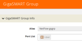
| 5. | Click Save. |
Notes:
| • | To use NetFlow, the GigaSMART Group can only contain one GigaSMART engine port. |
| • | Only one NetFlow Generation Monitor can be configured per GigaSMART Group. |
Step 2: Configure the NetFlow Exporter
Configure one or more NetFlow Generation Exporters. There can be up to six NetFlow Generation Exporters for each NetFlow Generation Monitor.
To configure the NetFlow Exporter, do the following:
| 1. | From the device view, select GigaSMART > NetFlow / IPFIX Generation > Exporters. |
| 2. | Click New. The NetFlow Exporters page shown in Figure 863: NetFlow Exporter Page displays. |
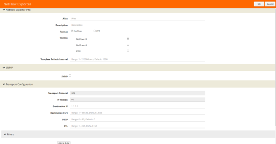
Figure 863: NetFlow Exporter Page
| 3. | On the NetFlow Exporter page, enter the information for the exporter. Table 2: NetFlow Exporter Configuration Fields describes the fields. |
Note: The NetFlow version must be configured with the same version of the Exporter and the Record. If no version is specified, version 9 is the default.
| 4. | Under the Filters section, click Add a Rule to create a filter for the exporter. |
| 5. | Click Save. |
.
|
Field |
Description |
|
Alias |
The alias name for the NetFlow Exporter. |
|
Description |
An optional description of the NetFlow record. |
|
Format |
The format is either NetFlow or CEF. |
|
Version |
The version is either NetFlow-v9, NetFlow-v5, or IPFIX. |
|
Template Refresh Interval |
After each template-refresh-interval, the record template is sent to the collector. Also, the option template is sent. |
|
SNMP |
Enables SNMP packet support on IP interfaces associated with the NetFlow Exporter. |
|
Transport Protocol |
The UDP port of the collector. This value cannot be changed. |
|
IP Version |
IP Version of the destination IP. Default is set as v4. It cannot be changed. |
|
Destination IP |
The IP address of the NetFlow/IPFIX collector. Default is set as 0.0.0.0. |
|
Destination Port |
Port for the destination IP. Default is set as 2055. |
|
DSCP |
The DSCP priority of the packet. Default is set as 0. |
|
TTL |
The Time to Live of the packet. Default is set as 64. |
Step 3: Configure an IP Interface
In this step, you identify the collector port and configure it as a tool port, where the NetFlow collector will be connected, and then configure an IP interface. The steps are as follows:
| 1. | Select the port to use and configure it as a tool port. |
| a. | Select Ports > Ports > All Ports. |
| b. | Click the Quick Port Editor button to open the Quick Port Editor. |
| c. | In the Quick Port Editor select the port to use for the IP interface, provide an alias to help identify the port (for example, NetFlow_Tunnel_Port), select Tool for the port type, and select Enable. |
| d. | Click OK. |
| 2. | Select Ports > IP Interfaces. |
| 3. | Click New. |
| 4. | On the IP Interface page, do the following: |
| a. | In the Alias and Comment fields, enter a name and description for the IP interface. |
| b. | From the Port drop-down list, select the tool port that you configured in Step 1. |
| c. | Select the type of IP interface as either IPv4 or IPv6. |
| d. | Enter the IP Address, IP Mask, Gateway address, and MTU value. |
| e. | From the GigaSMART Group drop-down list, select the GigaSMART group you created in Step 1: Configure a GigaSMART Group. |
| f. | From the Exporters drop-down list, select the NetFlow exporter you created in Step 2: Configure the NetFlow Exporter. |
Step 4: Configure the NetFlow Record
Configure a NetFlow Generation Record that has the following:
| • | match parameters that identify unique flows |
| • | collect parameters that identify fields you want to collect for the unique flows |
To configure the NetFlow Record, do the following:
| 1. | From the device view, select GigaSMART > NetFlow / IPFIX Generation > Records. |
| 2. | Click New. The NetFlow record page shown in Figure 864: NetFlow Record Page displays. |
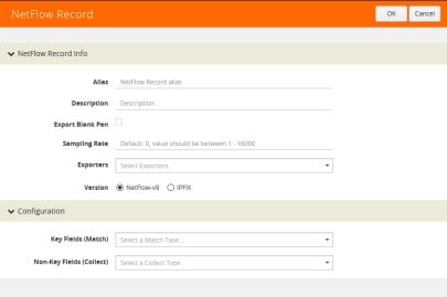
Figure 864: NetFlow Record Page
| 3. | On the NetFlow Record page, do the following: |
| a. | Specify the NetFlow Record information: |
| • | Enter an alias to help identify the record |
| • | Enter a Description (optional) |
| • | Enter the Sampling Rate that you want |
| • | Select the Exporter that you want from the Exporters menu |
| • | Select the Version |
The Version is either NetFlow-v9 or IPFIX. The NetFlow version must be configured with the same version of the Exporter and the Record. NetFlow-v9 is the default.
The Sampling Rate is multi-rate only, and is specified as 1 in N, where N is the packet count. The packet count can be a number from 1 to 16000. Refer to Sampled NetFlow Data. The Sampling Rate is disabled by default.
NetFlow-v9 and IPFIX let you configure Match/Key and Collect/Non-Key elements.
Make sure that you configure the NetFlow version prior to configuring the match and collect parameters because the subsequent parameters depend on the NetFlow version configured.
| b. | Specify the Configuration: |
Key Fields (Match) — the parameters that identify unique flows. The available Match/Key fields are based on the configured NetFlow version
Non-Key Fields (Collect) — the parameters that identify what you want to collect for the unique flows. The number of Collect/Non-Key elements in a record can be up to 32.
For details about the match and collect parameters, refer to NetFlow Generation Match/Key and Collect/Non-Key Elements
Step 5: Configure the NetFlow Monitor
Configure a NetFlow Generation Monitor and associate the NetFlow Generation Record to the specified NetFlow Generation Monitor by doing the following:
| 1. | From the device view, select GigaSMART > NetFlow / IPFIX Generation > Monitors. |
| 2. | Click New. The Monitors page shown in Figure 865: NetFlow Monitors Screen displays. |
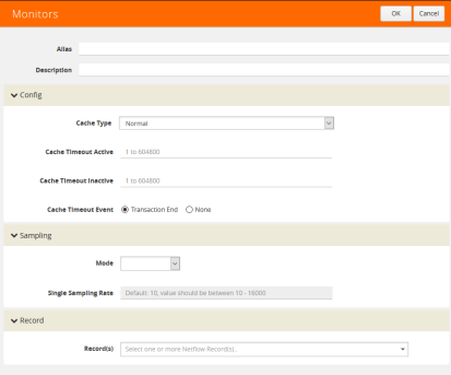
Figure 865: NetFlow Monitors Screen
| 3. | On the Monitors page, do the following: |
| a. | Enter an Alias to identify the monitor. |
| b. | Enter a Description (optional). |
| c. | Configure the Cache parameters. Refer to Table 3: NetFlow Monitor Parameters. |
| d. | Configure the Sampling parameters. Refer to Table 3: NetFlow Monitor Parameters. |
| e. | Select the Record that you configured in Step 4: Configure the NetFlow Record. |
| 4. | Click Save. |
|
Parameter |
Description |
|||||||||
|
Cache Type |
Set as Normal. |
|||||||||
|
Cache Timeout Active |
Despite the flow being active, it is “flushed out” to the Exporter after this timeout, which is set in seconds. |
|||||||||
|
Cache Timeout Inactive |
Inactive flows are “flushed out” to the Exporter after this timeout, which is set in seconds. |
|||||||||
|
Cache Timeout Event |
Applies to the TCP flow. The flow is “flushed out” to the Exporter after detecting a FIN or RST. |
|||||||||
|
Mode |
Select the sampling mode that you want:
|
|||||||||
|
Single Sampling Rate |
Refer to Sampled NetFlow Data. |
Step 6: Add the NetFlow Monitor to GigaSMART Group
Return to the GigaSMART Group configured in Step 1: Configure a GigaSMART Groupand set the NetFlow Monitor to the monitor created in Step 2: Configure the NetFlow Exporter.
| 1. | From the device view, select GigaSMART > GigaSMART Groups > GigaSMART Groups. |
| 2. | Select the GigaSMART Group configured in Step 1: Configure a GigaSMART Group, and then click Edit a shown in the following figure. |
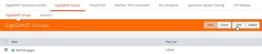
4Under GigaSMART Parameters, go to NetFlow. Click in the Monitor field and select the NetFlow monitor configured in Step 5: Configure the NetFlow Monitor as shown in the following figure.
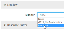
| 3. | Click Save. |
Step 7: Configure the GigaSMART Operation
Define a GigaSMART operation to enable NetFlow Generation. If combining NetFlow with APF or Deduplication GSOPs, make sure that you select both operations when creating the GigaSMART Operation.
To configure the GigaSMART Operation, do the following:
| 1. | From the device view, select GigaSMART > GigaSMART Operations (GSOP). |
| 2. | Click New. The GigaSMART Operations (GSOP) page displays. (Refer to Figure 866: GigaSMART Operation (GSOP) Page.) |
| 3. | On the GigaSMART Operations page, do the following: |
| a. | In the Alias field, enter a alias to help identify this gsop. |
| b. | In the GigaSMART Groups field, select the gsop configured in Step 1: Configure a GigaSMART Group. |
eIn the GigaSMART Operations (GSOP) field, select NetFlow. The NetFlow GigaSMART Operation is enabled by default as shown in Figure 866: GigaSMART Operation (GSOP) Page.
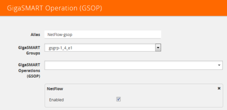
Figure 866: GigaSMART Operation (GSOP) Page
| 4. | Click Save. |
Step 8: Configure Mapping Rules to Filter Packets
To add flow mapping rules to filter packets that are needed to run NetFlow, configure a map and associate the map to the IP interface with tool port.
For more detailed information about flow mapping, refer to About Flow Mapping and Managing Maps.
Notes:
| • | For a single NetFlow GigaSMART Operation, make sure that you create a Regular By Rule map. When combining with APF or Deduplication, use First Level or Single Level map types. |
| • | Make sure that the other combining GigaSMART Operations are configured before creating maps using NetFlow. |
| • | When combining NetFlow with APF or Deduplication, create virtual ports to use with the second level maps. |
| • | The destination tool port must be the IP interface with tool port identified in Step 3: Configure an IP Interface |
For second level maps, you will need to create virtual ports. To create virtual ports, do the following:
| 1. | From the device view, select GigaSMART > Virtual Ports. |
| 2. | Click New. The Virtual Ports page shown in Figure 867: Virtual Ports Page displays. |
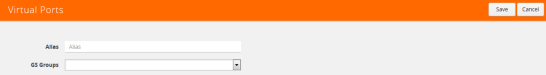
Figure 867: Virtual Ports Page
| 3. | Enter an alias in the Alias field to identify the virtual port. |
| 4. | In the GigaSMART Groups field, select the GigaSMART Group configured in Step 1: Configure a GigaSMART Group. |
| 5. | Click Save. |
To configure mapping rules to filter packets, do the following:
| 1. | Select Maps > Maps > Maps. |
| 2. | Click New to create a new map. |
| 3. | On the New Map page, do the following: |
| a. | Enter an alias in the Alias field and select the map Type and Subtype. |
| b. | Specify Source and Destination ports. |
| c. | In the GigaSMART Operations (GSOP) field, select the GigaSMART Operation configured in Step 7: Configure the GigaSMART Operation. |
| d. | Click Add a Rule to add the rules needed for the map. |
| 4. | Click Save. |
Configuring NetFlow Generation Examples
The following sections provide examples of NetFlow Generation. Refer to the following:
| • | Example 1: NetFlow Generation Configuration |
| • | Example 2: NetFlow Generation Configuration |
| • | Example 3: NetFlow Generation Configuration |
| • | Example 4: NetFlow Generation Configuration |
Example 1: NetFlow Generation Configuration
In Example 1, the steps set up a typical NetFlow Generation configuration.
Ex 1, Step 1: Configure the GigaSMART Group
Configure a GigaSMART group and associate it with a GigaSMART engine port.
Note: To use NetFlow, the gsgroup can only contain one GigaSMART engine port.
|
Step |
Description |
UI Steps |
||||||||||||||||||
|
Configure the GigaSMART Group |
|
||||||||||||||||||
|
Display the information about the GigaSMART Group. |
|
Ex 1, Step 2: Configure the NetFlow Generation Exporter
Configure one or more NetFlow Generation Exporters. There can be up to 6 NetFlow Generation Exporters for each NetFlow Generation Monitor.
The following parameters apply to this example:
| • | Transport Protocol — the UDP port of the collector. |
| • | Version — the version is either NetFlow-v9 or IPFIX. The NetFlow version must be configured with the same version of the Exporter and the Record. If no version is specified, version 9 is the default. |
| • | Template Refresh Interval — after each template-refresh-interval, the record template is sent to the collector. Also, the option template is sent. |
| • | SNMP — enables SNMP packet support for the NetFlow exporter. |
| • | Destination IP — the IP address of the NetFlow/IPFIX collector. |
| • | DSCP — the DSCP priority of the packet. |
| • | TTL — the Time to Live of the packet. |
|
Step |
Description |
UI Steps |
|||||||||||||||||||||
|
Configure the exporter. The exporter (exp4) will be used in Ex 1, Step 8: Configure Mapping Rules to Filter Packets. |
Alias: exp4. Version: IPFIX Template Refresh Interval: 60
Transport Protocol: UDP IP Version: v4 Destination IP: 20.20.20.20 Destination Port: 2055 DSCP: 10 TTL: 64
|
|||||||||||||||||||||
|
Display the exporter configuration. |
|
Ex 1, Step 3: Configure the IP Interface with Tool Port and Associate with the Exporter
Create an IP interface with tool port. You must associate this IP interface with the NetFlow Exporter you configured in Ex 1, Step 2: Configure the NetFlow Generation Exporter.
|
Step |
Description |
UI Steps |
|||||||||||||||||||||||||||||||||
|
Identify the collector port and configure it as a tool port, where the NetFlow collector will be connected. |
|
|||||||||||||||||||||||||||||||||
|
Configure the IP interface. The IP address is for the NetFlow interface. |
|
|||||||||||||||||||||||||||||||||
|
Display the IP interface configuration. |
|
Ex 1, Step 4: Configure the Record
Configure one or more NetFlow Generation Records, which have the following:
| • | Match parameters that identify unique flows |
| • | Collect parameters that identify fields you want to collect for the unique flows |
Note: NetFlow v9 and IPFIX let you configure Match/Key and Collect/Non-Key elements. For details refer to NetFlow Generation Match/Key and Collect/Non-Key Elements.
The following NetFlow Record parameters apply to this example:
| • | Version — the version is either NetFlow-v9 or IPFIX. The NetFlow version must be configured with the same version of the Exporter and the Record. If no version is specified, version 9 is the default. |
| • | Key Fields (Match) — the parameters that identify unique flows. The available Match/Key fields are based on the configured NetFlow version. |
| • | Non-Key Fields (Collect) — the parameters that identify what you want to collect for the unique flows. The number of Collect/Non-Key elements in a record can be up to 32. |
In this example, the IP source and destination address on the incoming traffic is used to identify network traffic between the unique pair of source and destination addresses. Once unique flows are identified, the following sample parameters are collected and exported for each flow:
| • | IP source and destination address |
| • | Total number of packets received that match the unique flows |
| • | IPv4 protocol |
| • | Transport source and destination ports |
| • | Input and output interface, plus interface name |
| • | Packet URL |
| • | DNS query name |
| • | Timestamp for the beginning and end of flow |
Note: Configure the NetFlow version prior to configuring the match and collect parameters because the subsequent parameters depend on the NetFlow version configured. If no version is specified, the version 9 is the default (NetFlow-v9).
|
Task |
Description |
UI Steps |
|||||||||||||||||||||||||||||||||||||||||||||||||||||||||||||||||||||||||||
|
Configure the record. The NetFlow version must be the same as the NetFlow version specified in Ex 1, Step 2: Configure the NetFlow Generation Exporter. The record (rec2) will be used in Ex 1, Step 5: Configure the Monitor. |
|
|||||||||||||||||||||||||||||||||||||||||||||||||||||||||||||||||||||||||||
|
Configure a second record. The NetFlow version must be the same as the NetFlow version specified in Ex 1, Step 2: Configure the NetFlow Generation Exporter. The match fields must be the same as in Step 1. Each record must have the same match fields but differing collect fields. The record (rec3) will be used in Ex 1, Step 5: Configure the Monitor. |
|
|||||||||||||||||||||||||||||||||||||||||||||||||||||||||||||||||||||||||||
|
Display the record configuration. |
|
Ex 1, Step 5: Configure the Monitor
Configure a NetFlow Generation Monitor and associate the NetFlow Generation Record to the specified NetFlow Generation Monitor.
The following parameters show the binding of the records. The parameters also define the cache (holding statistics for unique flows).
| • | Cache Timeout Event — Set to Transaction End. This applies to the TCP flow. The flow is “flushed out” to the Exporter after detecting a FIN or RST. |
| • | Cache Timeout Active — Despite the flow being active, it is “flushed out” to the Exporter after this timeout, which is set in seconds. |
| • | Cache Timeout inactive — Inactive flows are “flushed out” to the Exporter after this timeout, which is set in seconds. |
| • | Sampling — Enables sampled NetFlow and defines the sampling rate by specifying a number for 1 in N, where N is the packet count from 10 to 16000. |
| • | Records — Records generated for the flow are defined in the record and are stored in the internal cache. |
|
Step |
Description |
UI Steps |
|||||||||||||||||||||
|
Configure the monitor. The monitor (mon2) will be used in Ex 1, Step 8: Configure Mapping Rules to Filter Packets. The records (rec2 and rec3) were created in Ex 1, Step 4: Configure the Record. In this example, NetFlow sampling is enabled. The sampling rate is 1 in 1024. |
Cash Type: Normal Cash Timeout Event: Transaction End Cash Timeout Active: 60 Cash Timeout Inactive: 15 Sampling: 1024
Select rec2 Select rec3
|
|||||||||||||||||||||
|
Display the monitor configuration. |
|
Ex 1, Step 6: Add the monitor to the GigaSMART Group
Add the monitor created in Ex 1, Step 5: Configure the Monitor to the GigaSMART Group created in step Ex 1, Step 1: Configure the GigaSMART Group.
Note: Only one NetFlow Generation Monitor can be configured per gsgroup.
|
Step |
Description |
UI Steps |
||||||||||||||||||
|
Select the GigaSMART Group configured in Ex 1, Step 1: Configure the GigaSMART Group. |
|
||||||||||||||||||
|
Display the GigaSMART Group information. |
|
Ex 1, Step 7: Configure the GigaSMART Operation
Define a GigaSMART Operation to enable NetFlow Generation as follows:
|
Step |
Description |
UI Steps |
|||||||||||||||||||||
|
Configure the GigaSMART Operation and associate it with the GigaSMART Group created in Ex 1, Step 1: Configure the GigaSMART Group |
|
|||||||||||||||||||||
|
Display the configuration GigaSMART Operation. |
|
Ex 1, Step 8: Configure Mapping Rules to Filter Packets
To add flow mapping rules to filter packets that are needed to run NetFlow, configure a map and associate the map to the IP interface with tool port, as follows:
|
Step |
Description |
UI Steps |
|||||||||||||||||||||||||||
|
Configure the map. (This is a first level map.) |
Select IP Version. Set Version to 4.
|
|||||||||||||||||||||||||||
|
Display the map configuration. |
|
Example 2: NetFlow Generation Configuration
Starting in software version 4.2, NetFlow exporters can filter NetFlow records. The filtered NetFlow records are sent to the collectors.
In Example 2, there are three exporters, with filtering configured on two of them. Because the second exporter does not have any filtering configured, all the records are sent to the collector. In this example, there are also two tunnels and two maps. Both maps are first level maps.
Ex 2, Step 1: Configure the GigaSMART Group
Configure a GigaSMART group and associate it with a GigaSMART engine port, as follows:
|
Step |
Description |
UI Steps |
||||||||||||||||||
|
Configure the GigaSMART Group |
|
||||||||||||||||||
|
Display the information about the GigaSMART Group. |
|
Ex 2, Step 2: Configure the Exporters
Configure one or more NetFlow Generation Exporter(s), as follows:
|
Task |
Description |
UI Steps |
||||||||||||||||||||||||||||||||||||||||||||||||||||||||||||||||||||||||||||||||||||||||||||||||
|
Configure the first exporter. |
|
||||||||||||||||||||||||||||||||||||||||||||||||||||||||||||||||||||||||||||||||||||||||||||||||
|
Configure the second exporter. |
|
||||||||||||||||||||||||||||||||||||||||||||||||||||||||||||||||||||||||||||||||||||||||||||||||
|
Configure the third exporter. |
|
Ex 2, Step 3: Configure the IP Interfaces with Tool Ports and Associate with the Exporters
In this example, create two IP interfaces with tool ports. You must associate these IP interfaces with the NetFlow Exporters in Ex 2, Step 2: Configure the Exporters.
|
Task |
Description |
UI Steps |
||||||||||||||||||||||||||||||||||||
|
Identify the collector ports and configure them as a tool ports, where the NetFlow collector will be connected |
|
||||||||||||||||||||||||||||||||||||
|
Configure the first IP interface. |
|
||||||||||||||||||||||||||||||||||||
|
Configure the second IP interface. |
|
||||||||||||||||||||||||||||||||||||
|
Display the IP interfaces configurations. |
|
Ex 2, Step 4: Configure the Record
Configure a NetFlow Generation Record, as follows:
|
Task |
Description |
UI Steps |
|||||||||||||||||||||||||||||||||||||||
|
Configure the record. |
|
|||||||||||||||||||||||||||||||||||||||
|
Display the record configuration. |
|
Ex 2, Step 5: Configure the Monitor
Configure a NetFlow Generation Monitor and associate the NetFlow Generation Record to the specified NetFlow Generation Monitor, as follows:
|
Task |
Description |
UI Step |
||||||||||||||||||
|
Configure the monitor. Note: In this example, NetFlow sampling is not enabled. |
|
||||||||||||||||||
|
Display the monitor configuration. |
|
Ex 2, Step 6: Add the Monitor to the GigaSMART Group
Add the monitor created in Ex 1, Step 5: Configure the Monitor to the GigaSMART Group created in step Ex 1, Step 1: Configure the GigaSMART Group.
Note: Only one NetFlow Generation Monitor can be configured per gsgroup.
|
Step |
Description |
UI Steps |
||||||||||||||||||
|
Select the GigaSMART Group configured in Ex 2, Step 1: Configure the GigaSMART Group. |
|
||||||||||||||||||
|
Display the GigaSMART Group information. |
|
Ex 2, Step 7: Configure the GigaSMART Operation
Define a GigaSMART Operation to enable NetFlow Generation, as follows:
|
Step |
Description |
UI Steps |
|||||||||||||||||||||
|
Configure the GigaSMART Operation and associate it with the GigaSMART Group created in Ex 2, Step 1: Configure the GigaSMART Group |
|
|||||||||||||||||||||
|
Display the configuration GigaSMART Operation. |
|
Ex 2, Step 8: Configure Mapping Rules to Filter Packets
To add flow mapping rules to filter packets that are needed to run NetFlow, configure maps and associate the maps to the IP interfaces with tool ports, as follows:
|
Task |
Description |
UI Steps |
|||||||||||||||||||||||||||||||||||||||
|
Configure the first map. (This is a first level map.) |
|
|||||||||||||||||||||||||||||||||||||||
|
Configure the second map. (This is also a first level map.) |
|
|||||||||||||||||||||||||||||||||||||||
|
Display the map configuration. |
|
Example 3: NetFlow Generation Configuration
Starting in software version 4.3.01, NetFlow supports both first level and second level maps. In Example 3, there are two maps. However, unlike Example 2, which has two first level maps, in this example, one map is a first level map and the other is a second level map. A virtual port is configured that directs traffic to the second level map.
The configuration of the GigaSMART operation in Example 3 differs from Example 1 and Example 2. The GigaSMART Operation sends traffic to APF first, and then to NetFlow.
In the first level map, the traffic matching the rule is sent to the virtual port. The same traffic is also sent to two tool ports (2/1/g2 and 2/1/g3).
In the second level map, the traffic from the virtual port matching the gsrule is sent to NetFlow and then to the IP interface with tool port, 2/1/g7.
Ex 3, Step 1: Configure the GigaSMART Group
Configure a GigaSMART group and associate it with a GigaSMART engine port, as follows:
|
Step |
Description |
UI Steps |
||||||||||||||||||
|
Configure the GigaSMART Group |
|
||||||||||||||||||
|
Display the information about the GigaSMART Group. |
|
Ex 3, Step 2: Configure an IP Interface and Associated with the Exporter
Configure the IP interface and associate with the NetFlow Generation Exporter, as follows:
|
Task |
Description |
UI Steps |
||||||||||||||||||||||||||||||||||||
|
Configure the IP interface. |
|
Ex 3, Step 3: Configure the IP Interface with Tool Port
Create an IP interface with tool port.
|
Step |
Description |
UI Steps |
|||||||||||||||||||||||||||||||||
|
Identify the collector port and configure it as a tool port, where the NetFlow collector will be connected. |
|
|||||||||||||||||||||||||||||||||
|
Configure the IP interface. The IP address is for the NetFlow interface. |
|
|||||||||||||||||||||||||||||||||
|
Display the IP interface configuration. |
|
Ex 3, Step 4: Configure the Record
Configure a NetFlow Generation Record, as follows:
|
Task |
Description |
UI Steps |
||||||||||||||||||||||||
|
Configure the record. |
Select TOS. Select IPv4 and enable Source. Select Address.
Select IPv4 and enable Source. Select Interface.
|
Ex 3, Step 5: Configure the Monitor
Configure a NetFlow Generation Monitor and associate the NetFlow Generation Record to the specified NetFlow Generation Monitor, as follows:
|
Task |
Description |
UI Steps |
||||||||||||||||||
|
Configure the monitor. |
|
Ex 3, Step 6: Add the Monitor to the GigaSMART Group
Add the monitor created in Ex 3, Step 5: Configure the Monitor to the GigaSMART Group created in step Ex 3, Step 1: Configure the GigaSMART Group.
Note: Only one NetFlow Generation Monitor can be configured per gsgroup.
|
Step |
Description |
UI Steps |
||||||||||||||||||
|
Select the GigaSMART Group configured in Ex 3, Step 1: Configure the GigaSMART Group. |
|
||||||||||||||||||
|
Display the GigaSMART Group information. |
|
Ex 3, Step 7: Configure the GigaSMART Operation
Define a GigaSMART Operation to enable NetFlow Generation, as follows:
|
Step |
Description |
UI Steps |
|||||||||||||||||||||
|
Configure the GigaSMART Operation and associate it with the GigaSMART Group created in Ex 3, Step 1: Configure the GigaSMART Group |
|
|||||||||||||||||||||
|
Display the configuration GigaSMART Operation. |
|
Ex 3, Step 8: Configure the Virtual Port
For the second level map that you will create in Ex 3, Step 9: Configure Mapping Rules to Filter Packets, you will need to create a virtual port.
Configure a virtual port and associate it with the GigaSMART group, as follows:
|
Step |
Description |
UI Steps |
|||||||||||||||||||||
|
Configure the virtual port for the second level map. |
|
|||||||||||||||||||||
|
Display the virtual port information. |
|
Ex 3, Step 9: Configure Mapping Rules to Filter Packets
To add flow mapping rules to filter packets that are needed to run NetFlow, configure maps and associate the maps to the IP interface with tool port, as follows:
|
Task |
Description |
UI Steps |
|||||||||||||||||||||||||||||||||||||||
|
Configure the first map. (This is a first level map.) |
|
|||||||||||||||||||||||||||||||||||||||
|
Configure the second map. (This is a second level map.) |
|
Example 4: NetFlow Generation Configuration
Starting in software version 4.3.01, NetFlow supports both first level and second level maps. In Example 4, there are three maps. One map is a first level map and the other two are second level maps. Two virtual ports are configured that direct traffic to the second level maps.
Two GigaSMART operations are configured. One gsop sends traffic to masking. The other gsop sends traffic to APF and then to NetFlow.
In the first level map, the traffic matching the rule is sent to two virtual ports. The same traffic is also sent to a tool port (11/1/g3).
In the first second level map, the traffic from the first virtual port, vp1, that matches the gsrule, is sent to masking and then to the tool port 11/1/g2.
In the next second level map, the traffic from the second virtual port, vp2, that matches the gsrule, is sent to NetFlow and then to the IP interface with tool port, 11/1/g4.
Ex 4, Step 1: Configure the GigaSMART Group
Configure two GigaSMART groups and associate them with a GigaSMART engine port, as follows:
|
Step |
Description |
UI Steps |
||||||||||||||||||
|
Configure the first GigaSMART Group. |
|
||||||||||||||||||
|
Configure the second GigaSMART Group |
|
||||||||||||||||||
|
Display the information about the GigaSMART Group. |
|
Ex 4, Step 2: Configure the IP Interface with Tool Port
Create an IP interface with tool port. You must associated this IP interface with the NetFlow Exporter in Ex 4, Step 3: Configure the IP Interface and Associate with Exporter.
|
Step |
Description |
UI Steps |
|||||||||||||||||||||||||||||||||
|
Identify the collector port and configure it as a tool port, where the NetFlow collector will be connected. |
|
|||||||||||||||||||||||||||||||||
|
Configure the IP interface. The IP address is for the NetFlow interface. |
|
|||||||||||||||||||||||||||||||||
|
Display the IP interfaces configuration. |
|
Ex 4, Step 3: Configure the IP Interface and Associate with Exporter
Configure the IP interface and associate the NetFlow Generation Exporter, as follows:
|
Step |
Description |
Command |
||||||||||||||||||||||||||||||||||||
|
Configure the IP interface. |
|
Ex 4, Step 4: Configure the Record
Configure a NetFlow Generation Record, as follows:
|
Task |
Description |
UI Steps |
||||||||||||||||||||||||
|
Configure the record. |
Select IPV4 Select TOS and then select Source.
Select IPv4 and then select Protocol and Source Select Interface
|
Ex 4, Step 5: Configure the Monitor
Configure a NetFlow Generation Monitor and associate the NetFlow Generation Record to the specified NetFlow Generation Monitor, as follows:
|
Step |
Description |
Command |
|||||||||||||||||||||||||||
|
Configure the monitor. |
|
Ex 4, Step 6: Add the Monitor to the GigaSMART Group
Add the monitor created in Ex 4, Step 5: Configure the Monitor to the GigaSMART Group created in step Ex 4, Step 1: Configure the GigaSMART Group.
Note: Only one NetFlow Generation Monitor can be configured per gsgroup.
|
Step |
Description |
UI Steps |
||||||||||||||||||
|
Select the GigaSMART Group configured in Ex 4, Step 1: Configure the GigaSMART Group. |
|
||||||||||||||||||
|
Display the GigaSMART Group information. |
|
Ex 4, Step 7: Configure the GigaSMART Operation
Define the two GigaSMART operation to enable masking and NetFlow, as follows:
|
Step |
Description |
UI Steps |
||||||||||||||||||||||||
|
Configure the first GigaSMART Operation for APF and masking |
Protocol: None Offset: 50 Pattern: aa. Length: 100
|
||||||||||||||||||||||||
|
Configure the second GigaSMART Operation for NetFlow |
|
||||||||||||||||||||||||
|
Display the configuration GigaSMART Operation. |
|
Ex 4, Step 8: Configure the Virtual Port
For the second level map that you will create in Ex 4, Step 9: Configure Mapping Rules to Filter Packets, you will need to create virtual ports.
Configure a virtual port and associate it with the GigaSMART group, as follows:
|
Step |
Description |
UI Steps |
|||||||||||||||||||||
|
Configure the first virtual port for the second level map. |
|
|||||||||||||||||||||
|
Configure the second virtual port for the second level map. |
|
|||||||||||||||||||||
|
Display the virtual port information. |
|
Ex 4, Step 9: Configure Mapping Rules to Filter Packets
To add flow mapping rules to filter packets that are needed to run NetFlow, configure maps and associate the maps to the IP interfaces with tool ports, as follows:
|
Task |
Description |
UI Steps |
|||||||||||||||||||||||||||||||||||||||
|
Configure the first map. (This is a first level map.) |
|
|||||||||||||||||||||||||||||||||||||||
|
Configure the second map. (This is a second level map.) |
|
|||||||||||||||||||||||||||||||||||||||
|
Configure the third map. (This is also a second level map.) |
|
Displaying Exporter Statistics
To display exporter statistics, select GigaSMART > GigaSMART Operations (GSOP) > Statistics and open the GigaSMART Statistics Quick View to view the NetFlow Statistics.
Refer to NetFlow Exporter Statistics Definitions for descriptions of the statistics.
Displaying Monitor Statistics
To display exporter statistics, select GigaSMART > GigaSMART Operations (GSOP) > Statistics and open the GigaSMART Statistics Quick View to view the NetFlow Statistics.
Refer to NetFlow Monitor Statistics Definitions for descriptions of these statistics.
Displaying IP Interfaces Statistics
To display IP interfaces statistics, select Ports > IP Interfaces > Statistics and look for the IP interface ID in the statistics table.
Refer to IP Interfaces Statistics Definitions for descriptions of these statistics.
NetFlow Generation Configuration Modification and Removal
There may be instances where a NetFlow Generation configuration may require alteration by modifying a NetFlow Generation Monitor Configuration or a NetFlow Generation Record Configuration. It may further require that the configuration be removed entirely. In such instances, refer to the following.
Modifying a NetFlow Generation Monitor Configuration
This example shows the modification of a NetFlow Generation Monitor configuration.
| 1. | Unlink the monitor from GigaSMART Parameters. |
| a. | From the device view, select GigaSMART > GigaSMART Groups > GigaSMART Groups. |
| b. | Select the GigaSMART group to modify. |
| c. | Click Edit. |
| d. | Under NetFlow, select None in the Monitor field. |
| e. | Click Save. |
| 2. | Modify the monitor parameters. |
| a. | From the device view, select GigaSMART > NetFlow / IPFIX Generation > Monitors. |
| b. | Select the Monitor to modify. |
| c. | Click Edit. |
| d. | Under Config, modify the monitor parameters. |
| e. | Select the record from the Record(s) list to re-add it to the monitor. |
| 3. | Re-add the monitor to GigaSMART Parameters for the changes to take affect. |
| a. | From the device view, select GigaSMART > GigaSMART Groups > GigaSMART Groups. |
| b. | Select the GigaSMART group to modify. |
| c. | Click Edit. |
| d. | Under NetFlow, select the monitor in the Monitor field. |
| e. | Click Save. |
Modifying a NetFlow Generation Record Configuration
This example shows the modification of a NetFlow Generation Record configuration.
| 1. | Unlink the monitor from gsparams. |
| a. | From the device view, select GigaSMART > GigaSMART Groups > GigaSMART Groups. |
| b. | Select the GigaSMART group to modify. |
| c. | Click Edit. |
| d. | Under NetFlow, select None in the Monitor field. |
| e. | Click Save. |
| 2. | Modify the record bound to the monitor. |
| a. | From the device view, select GigaSMART > NetFlow / IPFIX Generation > Records. |
| b. | Select the record to modify. |
| c. | Click Edit. |
| d. | Modify the record configuration. |
| 3. | Re-add the monitor to the GigaSMART Parameters for changes in record to take affect. |
| a. | From the device view, select GigaSMART > GigaSMART Groups > GigaSMART Groups. |
| b. | Select the GigaSMART group to modify. |
| c. | Click Edit. |
| d. | Under NetFlow, select the monitor in the Monitor field. |
| e. | Click Save. |
Removing a NetFlow Generation Configuration
Use the following steps to remove a NetFlow Generation Configuration:
| 1. | Remove the NetFlow parameter from the GigaSMART Group. |
| a. | From the device view, select GigaSMART > GigaSMART Groups > GigaSMART Groups. |
| b. | Select the GigaSMART Group. |
| c. | Click Edit. |
| d. | Under NetFlow, select None in the Monitor field. |
| 2. | Delete the Maps. |
| a. | Select Maps > Maps > Maps. |
| b. | Select Table View. |
| c. | Select the Maps. |
| d. | Click Delete. |
| 3. | Delete the IP interface. |
| a. | Select Ports > IP Interfaces. |
| b. | Select the port. |
| c. | Click Delete. |
| 4. | Delete the monitor, records, and exporter |
| a. | From the device view, select GigaSMART > NetFlow / IPFIX Generation > Monitors. |
| b. | Select the monitor, and then click Delete. |
| c. | Select Records |
| d. | Select the record, and then click Delete |
| e. | Select Records. |
| f. | Select the record, and then click Delete. |
V5 Fixed Record Template
NetFlow v5 records have a template of fixed fields that cannot be edited. The template contains Match/Key and Collect/Non-Key elements. It has an alias of predefined_netflow_v5_record.
To display the template, select GigaSMART > NetFlow / IPFIX Generation > Records and click on predefined_netflow_v5_record to display the Record Quick View shown in Figure 868: NetFlow Record predefined_netflow_v5_record.
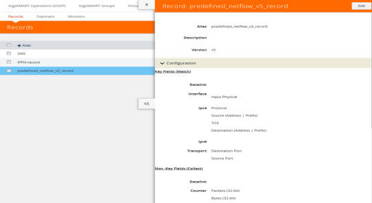
Figure 868: NetFlow Record predefined_netflow_v5_record
NetFlow Generation Match/Key and Collect/Non-Key Elements
NetFlow v9 and IPFIX records allow the user to configure Match/Key and Collect/Non-Key elements.
Match/Key Syntax
NetFlow v9 and IPFIX records allow the you to configure Match/Key elements.
Note: NetFlow v9 does not support Match/Key elements whose ID on the specified link is greater than 128. For additional information, refer to the following:
http://www.iana.org/assignments/ipfix/ipfix.xhtml
To configure the Match/Key elements, click in the Key Fields (Match) field in the NetFlow Record configuration page and select the match type.
The supported combinations of Match/Key elements are outlined in the following table:
|
Match Type |
Parameters |
|
|
Description |
|
Data Link |
Source |
|
|
Supported for v9 and IPFIX. |
|
|
Destination |
|
|
Supported for v9 and IPFIX. |
|
|
|
|
|
Supported for v9 and IPFIX. |
|
Interface |
Input physical |
Physical Width-2 Physical Width-4 |
|
Supported for v9 and IPFIX. for width, the only supported values are 2 or 4. |
|
IPv4 |
Destination |
Address |
|
Configures the IPv4 destination address as a key field. Supported for v9 and IPFIX. |
|
|
|
Prefix |
<netmask | mask_length> |
Configures a prefix for the IPv4 destination address as a key field. Supported for v9 and IPFIX. |
|
|
|
|
|
Supported only for IPFIX. |
|
|
Fragmentation Flags |
|
|
Supported only for IPFIX. |
|
|
Fragmentation ID |
|
|
Supported for v9 and IPFIX. |
|
|
Fragmentation Offset |
|
|
Supported for v9 and IPFIX. |
|
|
|
|
|
Supported only for IPFIX. |
|
|
|
|
|
Supported only for IPFIX. |
|
|
Precedence |
|
|
Supported only for IPFIX. |
|
|
Protocol |
|
|
Supported for v9 and IPFIX. |
|
|
Section |
Header Size |
<size> |
Configures the number of bytes of raw data starting at the IPv4 header, to use as a key field. The range is from 1 to 128. Supported only for IPFIX. |
|
|
|
Payload Size |
<size> |
Configures the number of bytes of raw data starting at the IPv4 payload, to use as a key field. The range is from 1 to 128. Supported only for IPFIX. |
|
|
Source |
Address |
|
Supported for v9 and IPFIX. |
|
|
|
Prefix |
<netmask | mask_length> |
Supported for v9 and IPFIX. |
|
|
TOS |
|
|
Supported only for IPFIX. |
|
|
Total Length |
maximum | minimum |
|
Supported only for IPFIX. |
|
|
TTL |
|
|
Supported only for IPFIX. |
|
|
Version |
|
|
Supported for v9 and IPFIX. |
|
IPv6 |
Destination |
Address |
|
Supported for v9 and IPFIX. |
|
|
|
Prefix |
<netmask | mask_length> |
Supported only for IPFIX. |
|
|
DSCP |
|
|
Supported only for IPFIX. |
|
|
Extension Map |
|
|
Supported for v9 and IPFIX. |
|
|
Flow Label |
|
|
Supported for v9 and IPFIX. |
|
|
Fragmentation Flags |
|
|
Supported only for IPFIX. |
|
|
Fragmentation ID |
|
|
Supported for v9 and IPFIX. |
|
|
Fragmentation Offset |
|
|
Supported for v9 and IPFIX. |
|
|
Hop Limit |
|
|
Supported only for IPFIX. |
|
|
Length |
Header |
|
Supported only for IPFIX. |
|
|
|
Payload |
|
Supported only for IPFIX. |
|
|
|
Total |
|
Supported only for IPFIX. |
|
|
Next Header |
|
|
Supported only for IPFIX. |
|
|
payload-length |
|
|
Supported only for IPFIX. |
|
|
Precedence |
|
|
Supported only for IPFIX. |
|
|
Protocol |
|
|
Supported for v9 and IPFIX. |
|
|
Section |
Header Size |
<size> |
Supported only for IPFIX. The range is from 1 to 128. |
|
|
|
Payload Size |
<size> |
Supported only for IPFIX. The range is from 1 to 128. |
|
|
Source |
Address |
|
Supported for v9 and IPFIX. |
|
|
|
Prefix |
<netmask | mask_length> |
Supported only for IPFIX. |
|
|
Traffic Class |
|
|
Supported for v9 and IPFIX. |
|
|
Version |
|
|
Supported for v9 and IPFIX. |
|
Transport |
Destination Port |
|
|
Supported for v9 and IPFIX. |
|
|
ICMP |
IPv4 |
Code |
Supported only for IPFIX. |
|
|
|
|
Type |
Supported only for IPFIX. |
|
|
|
IPv6 |
Code |
Supported only for IPFIX. |
|
|
|
|
Type |
Supported only for IPFIX. |
|
|
Source Port |
|
|
Supported for v9 and IPFIX. |
|
|
TCP |
ACK Number |
|
Supported only for IPFIX. |
|
|
|
Destination Port |
|
Supported only for IPFIX. |
|
|
|
Flags <enable | disable> |
[ACK] | [CWR] | [ECE] | [FIN] | [PSH] | [RST] | [SYN] | [URG] |
Supported only for v9 and IPFIX. |
|
|
|
Header Length |
|
Supported only for IPFIX. |
|
|
|
Sequence Number |
|
Supported only for IPFIX. |
|
|
|
Source Port |
|
Supported only for IPFIX. |
|
|
|
Urgent Pointer |
|
Supported only for IPFIX. |
|
|
|
window-size |
|
Supported only for IPFIX. |
|
|
UDP |
Destination Port |
|
Supported only for IPFIX. |
|
|
|
Message Length |
|
Supported only for IPFIX. |
|
|
|
Source Port |
|
Supported only for IPFIX. |
Collect/Non-Key Syntax
NetFlow v9 and IPFIX records allow the user to configure Collect/Non-Key elements.
The number of Collect/Non-Key elements in a record can be up to 32. Each Collect/Non-Key element has a size. The accumulated size of the Collect/Non-Key elements in the record cannot exceed 1024 bytes. The supported Collect/Non-Key elements is determined either by the maximum number of elements in a record (32) or by the maximum size (1024 bytes), whichever is reached first.
Note: NetFlow v9 does not support Collect/Non-Key elements whose ID on the specified link is greater than 128. For additional information, refer to the following:
http://www.iana.org/assignments/ipfix/ipfix.xhtml
To configure the Collect/Non-Key elements, click in the Non-Key Fields (Collect) field in the NetFlow Record configuration page and select the match type.
The supported combinations of Collect/Non-Key elements are outlined in the following table:
|
Collect Type |
Parameters |
Size |
|
Description |
|
Counter |
|
32 64 |
|
Supported for v9 and IPFIX. |
|
|
Packets |
32 64 |
|
Supported for v9 and IPFIX. |
|
Datalink |
Source |
|
|
Supported for v9 and IPFIX. |
|
|
|
|
|
Supported for v9 and IPFIX. |
|
|
|
|
|
Supported for v9 and IPFIX. |
|
Flow |
|
|
|
Supported only for IPFIX. |
|
Interface |
Input Name |
Input Width |
[width] |
Supported for v9 and IPFIX. for width, the range is from 1 to 32. |
|
|
Physical |
Physical Width-2 Physical Width-4 |
|
Supported for v9 and IPFIX. For width, the only supported values are 2 or 4. |
|
|
Output |
Physical Width-2 Physical Width-4 |
|
Supported for v9 and IPFIX. For width, the only supported values are 2 or 4. |
|
IPv4 |
Destination |
Address |
|
Configures the IPv4 destination address as a non-key field. Supported for v9 and IPFIX. |
|
|
|
Prefix |
<netmask | mask_length> |
Supported for v9 and IPFIX. |
|
|
|
|
|
Supported only for IPFIX. |
|
|
Fragmentation Flags |
|
|
Supported only for IPFIX. |
|
|
Fragmentation ID |
|
|
Supported for v9 and IPFIX. |
|
|
Offset |
|
|
Supported for v9 and IPFIX. |
|
|
|
|
|
Supported only for IPFIX. |
|
|
|
|
|
Supported only for IPFIX. |
|
|
Precedence |
|
|
Supported only for IPFIX. |
|
|
Protocol |
|
|
Supported for v9 and IPFIX. |
|
|
Section |
Header Size |
<size> |
Configures the number of bytes of raw data starting at the IPv4 header, to use as a key field. The range is from 1 to 128. Supported for v9 and IPFIX. |
|
|
|
Payload Size |
<size> |
Configures the number of bytes of raw data starting at the IPv4 payload to use as a key field. The range is from 1 to 128. Supported for v9 and IPFIX. |
|
|
Source |
Address |
|
Supported for v9 and IPFIX. |
|
|
|
Prefix |
<netmask | mask_length> |
Configures a prefix for the IPv4 destination address as a non-key field. Supported for v9 and IPFIX. |
|
|
TOS |
|
|
Supported only for IPFIX. |
|
|
Total Length |
[maximum] |
|
Supported only for IPFIX. |
|
|
|
[minimum] |
|
Supported only for IPFIX. |
|
|
TTL |
|
|
Supported only for IPFIX. |
|
|
Version |
|
|
Supported for v9 and IPFIX. |
|
IPv6 |
Destination |
Address |
|
Supported for v9 and IPFIX. |
|
|
|
Prefix |
<netmask | mask_length> |
Supported only for IPFIX. |
|
|
DSCP |
|
|
Supported only for IPFIX. |
|
|
Extension Map |
|
|
Supported for v9 and IPFIX. |
|
|
Flow Label |
|
|
Supported for v9 and IPFIX. |
|
|
Fragmentation Flags |
|
|
Supported only for IPFIX. |
|
|
Fragmentation ID |
|
|
Supported for v9 and IPFIX. |
|
|
Fragmentation Offset |
|
|
Supported for v9 and IPFIX. |
|
|
Hop Limit |
[maximum] |
|
Supported only for IPFIX. |
|
|
|
[minimum] |
|
Supported only for IPFIX. |
|
|
Length |
Header |
|
Supported for v9 and IPFIX. |
|
|
|
Payload |
|
Supported only for IPFIX. |
|
|
|
Total |
[maximum] |
Supported only for IPFIX. |
|
|
|
|
[minimum] |
Supported only for IPFIX. |
|
|
Next Header |
|
|
Supported only for IPFIX. |
|
|
Precedence |
|
|
Supported only for IPFIX. |
|
|
Protocol |
|
|
Supported for v9 and IPFIX. |
|
|
Section |
Header Size |
<size> |
Supported only for IPFIX. The range is from 1 to 128. |
|
|
|
Payload Size |
<size> |
Supported only for IPFIX. The range is from 1 to 128. |
|
|
Source |
Address |
|
Supported for v9 and IPFIX. |
|
|
|
Prefix |
<netmask | mask_length> |
Configures a prefix for the IPv4 destination address as a non-key field. Supported only for IPFIX. |
|
|
Traffic Class |
|
|
Supported for v9 and IPFIX. |
|
|
Version |
|
|
Supported for v9 and IPFIX. |
|
Private |
PEN <pen name> |
DNS |
|
Supported only for IPFIX. |
|
Private (continued) |
PEN <pen name> |
DNS |
|
Supported only for IPFIX. |
|
Private |
PEN <pen name> |
HTTP |
Response Code |
Supported only for IPFIX. |
|
Private |
PEN <pen name> |
HTTP |
URL |
Supported only for IPFIX. For width, the range is from 1 to 250. |
|
Private |
PEN <pen name> |
HTTP |
User Agent |
Supported only for IPFIX. For width, the range is from 1 to 250. |
|
Private |
PEN <pen name> |
SSL Certificate |
<Issuer [width] | |
Supported only for IPFIX. For width of Issuer and Subject, the range is from 1 to 250. For width of Issuer Common Name, Subject Alternative Name, and Subject Common Name, the range is from 1 to 64. |
|
Private |
PEN <pen name> |
SSL Server |
<Cipher | |
Supported only for IPFIX. For width, the range is from 1 to 64. |
|
Private |
PEN <pen name> |
URL |
[width] |
Supported only for IPFIX. For width, the range is from 1 to 250. |
|
timestamp |
Sys-uptime First |
|
|
Supported for v9 and IPFIX. |
|
|
Sys-uptime First Last |
|
|
Supported for v9 and IPFIX. |
|
transport |
Destination Port |
|
|
Supported for v9 and IPFIX. |
|
|
ICMP |
IPv4 Code |
|
Supported only for IPFIX. |
|
|
|
IPv4 Code Type |
|
Supported only for IPFIX. |
|
|
|
ipv6 Code |
|
Supported only for IPFIX. |
|
|
|
ipv6 Type |
|
Supported only for IPFIX. |
|
|
Source Port |
|
|
Supported for v9 and IPFIX. |
|
|
TCP Flags |
[ACK] | [CWR] | [ECE] | [FIN] | [PSH] | [RST] | [SYN] | [URG] |
|
Supported for v9 and IPFIX. |
|
|
TCP |
ACK Number |
|
Supported only for IPFIX. |
|
|
|
Destination Port |
|
Supported only for IPFIX. |
|
|
|
Header Length |
|
Supported only for IPFIX. |
|
|
|
Sequence Number |
|
Supported only for IPFIX. |
|
|
|
Source Port |
|
Supported only for IPFIX. |
|
|
|
Urgent Pointer |
|
Supported only for IPFIX. |
|
|
|
Window Size |
|
Supported only for IPFIX. |
|
|
UDP |
Destination Port |
|
Supported only for IPFIX. |
|
|
|
Message Length |
|
Supported only for IPFIX. |
|
|
|
Source Port |
|
Supported only for IPFIX. |


