Configuration Steps
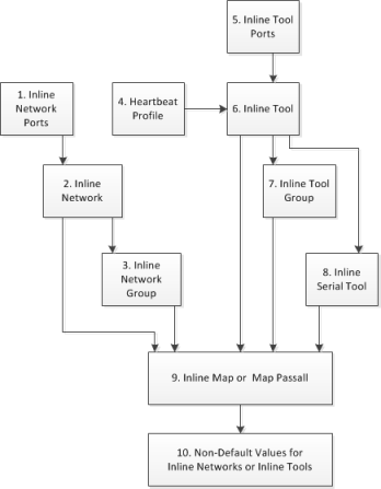
The configuration steps in summary for an inline bypass solution are as follows:
|
1.
|
Configure inline network ports. (Optional for protected inline network.) |
|
2.
|
Configure inline network. (Optional for protected inline network.) |
|
3.
|
(Optional) Configure inline network group. |
|
4.
|
(Optional) Configure heartbeat or negative heartbeat profile. |
|
5.
|
Configure inline tool ports. |
|
6.
|
Configure inline tool. |
|
7.
|
(Optional) Configure inline tool group. |
|
8.
|
(Optional) Configure inline tool series. |
|
9.
|
Configure inline maps, either passall, map (rule-based), map shared collector, or bypass. |
|
10.
|
Configure non-default values for parameters of the inline networks or inline tools. |
The summary steps are shown in 1.
|
1
|
Configuration Steps for Inline Bypass Solutions |
The configuration details for an inline bypass solution are as follows:
|
1.
|
Configure inline network ports. (Optional for protected inline network.) |
The configuration begins with defining the inline network ports that will participate in the inline network. Use Quick Port Editor to configure a port type of inline-network.
For an unprotected inline network, you configure the inline network ports.
For a protected inline network, the ports are created automatically when the bypass combo modules are recognized by the GigaVUE HC Series node.
For detailed steps, refer to Configure Inline Network Ports.
|
2.
|
Configure inline network. (Optional for protected inline network.) |
Next configure the inline network or inline networks using the inline Network configuration page and the port pairs defined in step 1.
For an unprotected inline network, you configure the inline network.
For a protected inline network, the inline network is created automatically when the bypass combo modules are recognized by the GigaVUE HC Series node.
In either case, the inline network will have parameters set to default values, such as, the Traffic Path will be set to Bypass and the Physical Bypass will enable.
The initial forwarding state of the unprotected inline network will be DISABLED. The initial forwarding state of the protected inline network will be PHYSICAL BYPASS.
For detailed steps, refer to Configure Inline Network (Unprotected).
|
3.
|
(Optional) Configure inline network group. |
If the inline bypass solution involves an inline network group, first configure the participating inline networks before configuring the inline network group. Use the Inline Network Group configuration page to configure the inline network group and see the list of inline networks defined in step 2 by selecting Inline Bypass > Inline Network Groups.
For detailed steps, refer to Configure Inline Network Group
|
4.
|
(Optional) Configure heartbeat or negative heartbeat profile. |
If any of the inline tools will be using a heartbeat profile, a default heartbeat profile is provided, so no configuration is needed except a name. However, if any of the inline tools will be using a heartbeat profile with non-default settings, first configure the heartbeat profile using the Heartbeats configuration page, before configuring the inline tools that will use that profile.
If any of the inline tools will be using a negative heartbeat profile, configure the negative heartbeat profile by providing an alias and a PCAP file using the Heartbeats configuration page, before configuring the inline tools that will use that profile
For detailed steps, refer to Create Heartbeat Profile and Create Negative Heartbeat Profile.
|
5.
|
Configure inline tool ports. |
Next configure inline tool ports. Use Quick Port Editor to configure the ports a port type of Inline Tool
For detailed steps, refer to Configure Inline Tool Ports.
|
6.
|
Configure inline tool. |
Next configure the inline tool or inline tools using the inline Tool configuration page and the port pairs defined in step 5.
For detailed steps, refer to Configure Inline Tool.
|
7.
|
(Optional) Configure inline tool group. |
If the inline bypass solution involves an inline tool group, first configure the participating inline tools, before configuring the inline tool group. Use the inline Tool Group configuration page to configure the inline tool groups and see the list the inline tools defined in step 6 by selecting Inline Bypass > Inline Tool Groups.
For detailed steps, refer to Create Inline Tool Group.
|
8.
|
(Optional) Configure inline tool series. |
If the inline bypass solution involves an inline tool series, first configure the participating inline tools, before configuring the inline tool series. Use the inline Serial Tools Group configuration page and list the inline tools defined in step 6 by selecting Inline Bypass > Inline Serial Tools.
|
9.
|
Configure inline maps, either map passall, map (rule-based), or map shared collector. |
The next configuration step is to configure inline maps that specify how to direct the traffic from the configured inline networks and inline network groups to the configured inline tools, inline tool groups, and inline tool series. You can configure either a map passall, a map (rule-based), or a map shared collector. Create a map with type Inline and a subtype of ByRule, Pass All, or Collector.
For details about configuring maps, refer to Manage Maps.
Note: Classic Inline Maps must have the source and destination inline components residing in the same device. Therefore, it will not support the inline flow maps with source and destination inline components across nodes in a cluster.
|
10.
|
Configure non-default values for parameters of the inline networks or inline tools. |
Now configure non-default values for inline network parameters. For example, for an unprotected inline network, when you change the Traffic Path to To Inline Tool, traffic will start flowing through the inline tools from the unprotected inline network. For a protected inline network, when you uncheck Physical Bypass, traffic will start flowing through the inline tools from the protected inline network.
For protected inline networks, to start the traffic flowing, perform the following steps under Configuration on the Inline Network configuration page:
|
1.
|
Change the Traffic Path to To Inline Tool. |
|
2.
|
Uncheck the Physical Bypass. |
Configuration Step Details
This section provides detailed steps for configuring inline bypass through the GigaVUE‑OS H-VUE UI.
Configure Inline Network Ports
Use the following procedure to create inline network ports:
|
1.
|
From the left navigation pane, go to System > Ports > Ports > All Ports. |
|
2.
|
Open Quick Port Editor by clicking the Port Editor button. |
|
3.
|
Use the Quick search field to Find the ports to configure. |
|
4.
|
In th an Alias field enter a name to help identify the inline port. |
|
5.
|
For Type, select Inline Network. |
An Inline Network (unprotected) is a software arrangement of two network-type ports allocated to facilitate access to a bidirectional link between two networks (far end network devices) that are linked to inline tool ports.
Note: Any available network-type ports on a Gigamon node can be used to form an unprotected inline network.
Configure Inline Network (Unprotected)
An Inline Network Group is an arrangement of multiple inline network ports to which traffic is distributed based on calculated hash values used by a Gigamon node.
Perform the steps to configure an inline network:
|
1.
|
After configuring the Inline Network ports, select Inline Bypass > Inline Networks. |
|
3.
|
In the Alias field, enter an alias for the inline network to help identify the inline network. |
|
4.
|
From the Port A drop-down list select an inline network port. |
|
5.
|
An inline network port is automatically selected for Port B. To select a different port, select one from the Port B drop-down list if there is more than one inline network port. |
|
6.
|
Select a traffic path from the Traffic Path drop-down list. The types of traffic paths are: |
|
o
|
Bypass — All traffic arriving at the Port A inline network port is directly forwarded to the Port B inline network port and all traffic arriving at the Port B inline network port is directly forwarded to the Port A inline network port. |
|
o
|
Drop — No traffic is exchanged through the inline network ports (all traffic coming to these ports is dropped). |
|
o
|
ByPass with Monitoring — All traffic is forwarded as a forced bypass value and a copy of the traffic is also forwarded to the inline tools. A traffic map must first be configured between the inline network and the inline tool to have the traffic forwarded with no traffic taken from the inline tools. |
|
o
|
To Inline Tool — The traffic received at the inline network ports is forwarded based on: |
1. The traffic map between the inline network and the respective inline tools.
2. The failover action attributes of the inline tools
3. The health state of the inline tools.
|
7.
|
Select the Link Propagation check box to enable whether the inline network link on one side of the inline network gets propagated to the other side. |
Configure Inline Network Group
An Inline Network Group is an arrangement of multiple inline network ports to which traffic is distributed based on calculated hash values used by Gigamon node.
Perform the following steps to configure an Inline Network Group:
|
1.
|
After configuring the Inline Network Ports, select Inline Bypass > Inline Network Groups. |
|
3.
|
In the Alias field, enter a name for the network group. |
|
4.
|
From the Inline Network drop-down list, select the Inline Network ports. |
Create Heartbeat Profile
The Heartbeat Profile is a data structure that contains the heartbeat attributes that are applied to an Inline Tool for configuring its heartbeat. The Create Heartbeat Profile wizard allows you to apply attribute values for the heartbeat profile. Use the following procedure:
|
1.
|
Select Inline Bypass > Heartbeats. |
|
3.
|
In the Alias field, enter a name for your heartbeat profile. |
|
4.
|
In the Type field, select Regular. |
For details about regular heartbeats, refer to Standard Heartbeat.
|
5.
|
Use Packet Format drop-down list to select a packet type. The formats are: |
|
o
|
ARP—This protocol (Address Resolution Protocol) is used for resolution of network layer address into link layer addresses, which is critical for multiple-access network operation. ARP is the default. |
|
o
|
Custom—This format is a binary packet content associated with a packet capture (pcap) file. For details about custom packet format, refer to Standard or Custom Heartbeat Packet. |
When you select Custom, a Custom Format field displays with a Browse button. Use the Browse button to upload the pcap file.
|
6.
|
Use the Direction drop-down menu to select the direction for sending heartbeat. The directions are: |
|
o
|
A to B—From Port A to Port B of the inline tool. |
|
o
|
B to A—From Port B to Port A of the inline tool. |
|
o
|
Bi-directional—Both directions. |
|
7.
|
In the Timeout field, enter a number in milliseconds to indicate a timeout period for heartbeat packets between sending and receiving. The acceptable range is 20 to 1000 milliseconds. The default is 500 milliseconds. |
|
8.
|
In the Period field, enter a number in milliseconds for sending subsequent heartbeat packets. The acceptable range is 30 to 5000 milliseconds. The default is 1000 milliseconds. |
|
9.
|
In the Recovery Time field, enter a number in seconds to indicate that the inline tool is declared up with successfully receiving packets. The acceptable range is 5 to 60 seconds. The default is 30 seconds. |
|
10.
|
In the Retries field, enter the number for consecutive timed-out heartbeat packets at which the system will trigger (retry) a fail over condition. |
The heartbeat profile appears in the Heartbeat Profile table.
Note: Highlight the heartbeat profile and click Edit to modify the parameters, if needed.
Create Negative Heartbeat Profile
The Negative Heartbeat Profile is a data structure that contains the negative heartbeat attributes that are applied to an Inline Tool for configuring its negative heartbeat. The Create Heartbeat Profile wizard allows you to apply attribute values for the negative heartbeat profile. Use the following procedure:
|
1.
|
Select Inline Bypass > Heartbeats. |
|
3.
|
In the Alias field, enter a name for your heartbeat profile. |
|
4.
|
In the Type field, select Negative |
This is a negative heartbeat profile. For details about negative heartbeats, refer to Negative Heartbeat Profiles.
|
5.
|
Use Browse button in the Custom Format field to upload binary packet content associated with a packet capture (pcap) file. For details about the custom format, refer to Standard or Custom Heartbeat Packet. |
|
6.
|
Use the Direction drop-down menu to select the direction for sending heartbeat. The directions are: |
|
o
|
A to B—From Port A to Port B of the inline tool. |
|
o
|
B to A—From Port B to Port A of the inline tool. |
|
o
|
Bi-directional—Both directions. |
|
7.
|
In the Period field, enter a number in milliseconds for sending subsequent negative heartbeat packets. The acceptable range is 30 to 5000 milliseconds. The default is 1000 milliseconds. |
|
8.
|
In the Recovery Time field, enter the minimum number of seconds since the last negative heartbeat packet is received to declare that the inline tool is up. |
The inline tool is up from the standpoint of the negative heartbeat if the negative heartbeats sent are not received. When a tool is declared down, sent heartbeats should not be received for a number of seconds in order to declare the tool as being up.
The acceptable range for the Recovery Time field is 5 to 60 seconds. The default is 30 seconds.
The heartbeat profile appears in the Heartbeat Profile table.
Note: Highlight the heartbeat profile and click Edit to modify the parameters, if needed.
Configure Inline Tool Ports
Use the following procedure to create inline tool ports:
|
1.
|
From the left navigation pane, go to System > Ports > Ports > All Ports. |
|
2.
|
Open Quick Port Editor by clicking the Port Editor button. |
|
3.
|
Use the Quick search field to Find the ports to configure. |
|
4.
|
In th an Alias field enter a name to help identify the inline port. |
|
5.
|
For Type, select Inline Tool. |
An Inline Tool represents a pair of inline tool ports.
Configure Inline Tool
An Inline Tool represents a pair of inline tool ports. To configure an Inline Tool, do the following:
|
1.
|
Select Inline Bypass > Inline Tools. |
|
3.
|
If needed, click Port Editor to open the Quick Port Editor to configure the inline tool ports. |
|
4.
|
Select the inline tool ports for the inline tool. |
|
5.
|
Select Enabled to set the inline tool ports as enabled for inline bypass traffic. |
|
6.
|
For Failover action, select one of the following: |
|
o
|
Tool Bypass — When the inline tool fails all traffic coming to the respective inline tool is directed via the bypass path. |
|
o
|
Network Bypass — When the inline tool fails the traffic is directed to multiple inline tools associated with an inline network or inline network group using rule-based inline maps. |
|
o
|
Tool Drop — When the inline tool fails all traffic coming to the respective inline tool is dropped. |
|
o
|
Network Drop—When the inline tool fails all traffic coming to the respective inline tool is dropped. |
|
o
|
Network Port Forced Down—When the inline tool fails the inline network ports of the respective inline network are forced as "down". |
|
7.
|
Select the Recovery Mode. The recovery mode can be one of the following: |
|
o
|
automatic—Specifies automatic recovery, which redirects traffic back to the inline tool as soon as it has recovered from all faulty conditions. |
|
o
|
manual—Specifies manual recovery, which lets you control when to put an inline tool back into service after the tool has recovered. For example, you may want to wait for a maintenance window to return the inline tool to service. |
|
8.
|
Select Enable Heartbeat to set the heartbeat. |
If the heartbeat is enabled, do the following:
|
a.
|
From Profile, select the desire heartbeat profile. The available heartbeat profiles are existing profiles from other inline tools. Once a heartbeat profile is selected, its attributes are displayed. |
|
b.
|
In the HB IP Address A field, enter the server's IP address to send the heartbeat packets. |
|
c.
|
In the HB IP Address B field, enter the server's IP address to send a second heartbeat packet. |
Create Inline Tool Group
An Inline Tool Group is an arrangement of multiple Inline Tools to which traffic is distributed based on calculated hash values used by Gigamon node.
To configure an Inline Tool Group, do the following:
|
1.
|
Use the Quick Port Editor to configure the inline tool ports. |
|
2.
|
Select Inline Bypass > Inline Tool Groups. |
|
4.
|
In the Alias field, enter a name to help identify the inline tool group. |
|
5.
|
For Inline Tools, select the inline tool ports for the inline tool group. |
|
6.
|
(Optional) For the Inline Spare Tool, select another inline tool port. |
If a spare is selected, the inline tool group becomes a redundant arrangement of inline tools. When the first failure occurs in a set of active inline tools, traffic will be forwarded to the spare with no loss, thus the spare will replace the failed tool in the active set.
|
7.
|
Select Enable to enable the inline tool group. |
|
8.
|
Select the Failover Action. The failover actions are: |
|
o
|
Tool Bypass—When the inline tool group fails all traffic coming to the respective inline network is directed via the bypass path. |
|
o
|
Tool Drop—When the inline tool group fails all traffic coming to the respective inline network is dropped. |
|
o
|
Network Bypass—When the inline tool group fails all traffic coming to the respective inline network is directed to the inline tool group via the bypass path. |
|
o
|
Network Drop—When the inline tool group fails all traffic coming to the respective inline network group is dropped. |
|
o
|
Network Port Forced Down—When the inline tool group fails the inline network ports of the respective inline network are forced as "down". |
|
9.
|
For Minimum Healthy Group Size, select a number that represents the minimal amount of inline tools that are required to have a state of Normal. |
|
10.
|
Select the Hash for the inline tool group. |
Hashing, which is used for distributing traffic across the inline tools in an inline tool group. The values for the hash parameter are as follows:
|
o
|
advanced—Specifies symmetrical hashing, which is derived from the combination of packet fields based on the criteria selected for the advanced-hash algorithm. For inline bypass applications, the most common choice of criteria for the advanced-hash algorithm is the combination of source IP and destination IP addresses. This produces a hash value that sends all traffic associated with the same session to the same inline tool in the inline tool group. |
|
o
|
a-srcip-b-dstip—Specifies asymmetrical hashing, which is derived from the source IP address for side A of the network and the destination IP address for side B of the network. This produces a hash value that sends all traffic associated with the same source address residing on side A to the same inline tool in the inline tool group, regardless of destination or session. |
|
o
|
b-srcip-a-dstip—Specifies asymmetrical hashing, which is derived from the destination IP address for side A of the network and the source IP address for side B of the network. This produces a hash value that sends all traffic associated with the same source address residing on side B to the same inline tool in the inline tool group, regardless of destination or session. |
Configure Inline Tool Series
To configure an Inline Tool Series, do the following:
|
1.
|
Select Inline Bypass > Inline Serial Tools. |
|
3.
|
In the Alias field, enter a name to help identify the inline tool series. |
|
4.
|
For Inline Tools, select the inline tool ports for the inline tool series. |
|
5.
|
Select Enabled to enable this configuration. |
|
6.
|
Select the Failover action. |
For details about the failover actions, refer to Inline Tool Series Local Failover Action
|
7.
|
Select the Per Direction Order. |
For details about per-direction order, refer to Inline Tool Series Per-Direction Order.
Configure When GigaVUE HC Series Modules are Operationally Up
Ensure that the GigaVUE HC Series modules are in the operationally up state before configuring them. Configuration changes done when a module is operationally down are not supported.
Also, when an inline tool or inline tool group is in the operationally down state, do not modify the current failover action of that inline tool or inline tool group until the tool has recovered from the failover state.
Avoid Oversubscription
In general, traffic received at inline network ports is delivered to the destination ports according to the inline maps and the out-of-band maps regardless of whether the destination ports have the capacity to absorb all the traffic or not.
Note: When an inline network is involved in an inline map or an out-of-band map to a destination port (tool port or inline tool port), when there is temporary oversubscription, some packets arriving at the inline network port will be dropped. This can happen when the traffic path is set to bypass or monitoring.
Ensure that destination ports of maps originating from inline network ports have enough capacity to absorb the amount of traffic coming to the inline network ports.


