About Inline Serial Tools
Use the Inline Serial Tools Groups configuration page to configure inline tools in a series, in which the traffic from one side of the inline network is guided through the members of the inline tool series before it is sent out the other side of the inline network. With inline tools and inline tools groups arranged in a series, the traffic from one inline tool or inline tool group flows to the next, so all tools see the same traffic.
The inline tool ports that make up the inline tools and inline tool groups participating in the inline tool series are always in pairs, running at the same speed, on the same medium (fiber or copper). All inline tool ports of the inline tool series must be on the same GigaVUE‑HC3, GigaVUE‑HC2, or GigaVUE‑HC1 node. The inline tool ports and inline tool groups must also be on the same GigaVUE‑HC3, GigaVUE‑HC2, or GigaVUE‑HC1 node as the inline network ports.
To view the currently configured inline tool series, select Inline Bypass > Inline Serial Tools to open the Inline Serial Tool Groups page shown in the following figure.
Refer to 1 for an illustration of an inline tool series. In 1, traffic is only shown from A-to-B.
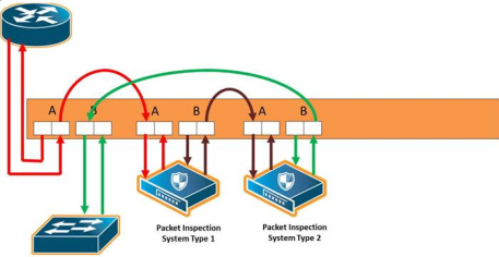
| 1 | Inline Serial Tools |
Refer to 2 Inline Tool Series, Including Inline Tool Group for an inline tool series that includes an inline tool group in addition to individual inline tools. The per-direction-order is set to forwarding. In 2, the inline tool group is placed as the middle member of the series, but it could be placed as the first member of the series or the last member of the series as well. In the inline tool group, traffic is shared.
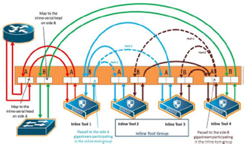
| 2 | Inline Tool Series, Including Inline Tool Group |
Note: For inline SSL decryption, the inline tool series does not support an inline tool group in the series.
The number of inline tools and inline tool groups in the inline series is limited only by the number of ports available for creating the inline networks and inline tools participating in the inline bypass solution.
When an inline tool group is included as a member of a inline series:
| a spare inline tool can be configured on the inline tool group |
| inline maps to individual members of an inline tool group are not supported |
| asymmetrical hashing is not supported, which means that the hash options, ascrip-b-dstip and b-scrip-a-dstip, are not allowed on the inline tool group. |
To configure an inline serial tool group, do the following:
| 1. | Open the Inline Serial Tool Group configuration page by selecting Inline Bypass > Inline Serial Tools from the main navigation pane, and then clicking New. |
| 2. | Enter a name for the inline serial tool group in the Alias field to identify the group and an optional description in the Description field. |
| 3. | Select and order the inline tools for the inline tool group. |
| a. | Click in the Inline Tools fields. The drop-down list shows the available inline tools |
| b. | Select the inline tools or in or inline tool group to add to the inline serial tool group. |
The inline tools are displayed in the order that they are selected. To change the order, click the up and down arrows.
| 4. | Click Save. |
Note: An inline serial tool group cannot be edited after it is saved.
Inline Serial Tools Global Failover Action
One of the parameters of inline tool series is the failover action taken in response to a failure of the inline tool series as a whole. This is referred to as the global failover action.
Each inline tool or inline tool group in the series can also have its own failover action. This is referred to as the local failover action. Refer to Inline Tool Series Local Failover Action for details.
For global failover actions, an inline tool series is declared to be in a failure condition as soon as any of its member inline tools goes into a failure condition. An inline tool series recovers from a failure condition after all the member inline tools recover from their failure conditions. The failover action attributes of the individual inline tools participating in an inline tool series are ignored. Instead, the Failover action configured on the Inline Serial Tool Group page for the inline tool series is executed. The values for global failover actions are as follows:
| ToolBypass—when the inline serial tools fails, the traffic that normally was directed to the inline tool is redirected to the bypass path. Use this failover action for configurations involving an inline serial tools that is associated with an inline network using rule-based maps. For configurations using map passalls, tool-bypass is the same as network-bypass. Refer to 3 Inline Tool Series Global Bypass Failover Action. |
| NetworkBypass—when the inline serial tools fails, all traffic that would not have been dropped when the inline network or networks had a NORMAL forwarding state is directed to the bypass path. That is, all such traffic arriving at the side A inline network port or ports is forwarded to the side B inline network port or ports and all traffic arriving at the side B inline network port or ports is forwarded to the side A inline network port or ports. Refer to 3 Inline Tool Series Global Bypass Failover Action. |
| NetworkPortForcedDown—when the inline serial tools fails, the inline network ports of the respective inline network are forced down. Refer to 4 Inline Tool Series Global Network Ports Forced Down Failover Action. |
| ToolDrop—when the inline serial tools fails, the traffic that normally was directed to the inline tool is dropped. Use this failover action for configurations involving an inline serial tools that is associated with an inline network using rule-based maps. For configurations using map passalls, tool-drop is the same as network-drop. Refer to 5 Inline Tool Series Global Drop Failover Action. |
| NetworkDrop—when the inline serial tools fails, all traffic coming to the respective inline network (or inline network group) is dropped. Refer to 5 Inline Tool Series Global Drop Failover Action. |
The bypass path is between side A and side B of the inline network ports.
The default is ToolBypass.
Any failure of any member leads to the failure of the inline serial tools, hence the failover action for an inline serial tools will overwrite the failover action of the inline tool members of the series.
3 to 5 show the global failover actions for the inline series when any individual inline tool in the series fails.
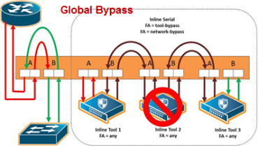
| 3 | Inline Tool Series Global Bypass Failover Action |
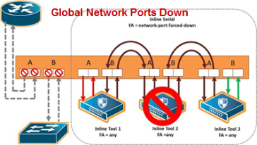
| 4 | Inline Tool Series Global Network Ports Forced Down Failover Action |
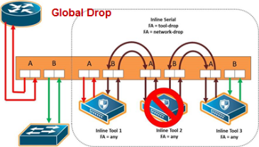
| 5 | Inline Tool Series Global Drop Failover Action |
Inline Tool Series Local Failover Action
Each inline tool in the series can have its own local failover action. When an individual inline tool or inline tool group in the series fails, the action taken depends on the failover action of the individual inline tool.
To configure local failover actions, configure a failover action of Per Tool for the series as a whole. Then the individual failover action for each inline tool in the series, as configured with the inline Tool failover action, takes effect. For details on the values, refer to Inline Tool Failover Action.
For example, if the failover action of the inline series is configured as Per Tool and the failover action of an individual inline tool in the series is configured as ToolBypass, when that tool in the series fails, the traffic will skip over the failed tool.
Note: For inline SSL decryption, the Per Tool failover action is not supported.
The values for local failover actions are as follows:
| ToolBypass—when the inline tool fails, the traffic bypasses the failed tool. That is, the traffic originally coming to the inline tool is diverted to the next inline tool in the series or to the appropriate inline network port if the inline tool is the last in the series. Refer to 6 Inline Tool Series Local Tool Bypass Failover Action. |
Note: When all the inline tools in a series are configured as ToolBypass and they all fail, this is the same as the failover action of ToolBypass for the series.
| ToolDrop—when the inline tool fails, traffic to this inline tool stops being forwarded. Effectively, this has the same result as the failover action of ToolDrop for the series as a whole, although the healthy members of the series will still receive traffic in one of the directions. Refer to 7 Inline Tool Series Local Tool Drop Failover Action. |
| NetworkBypass—when the inline tool fails, a bypass is established between the inline network ports. Refer to 8 Inline Tool Series Local Network Bypass Failover Action. |
| NetworkDrop—when the inline tool fails, traffic is dropped at the inline network ports. Refer to 9 Inline Tool Series Local Network Drop Failover Action. |
| NetworkPortForcedDown—when the inline tool fails, the links for the inline network ports are brought down. Refer to 10 Inline Tool Series Local Network Ports Forced Down Failover Action. |
6 to 10 show the local failover actions when an individual inline tool in a series fails
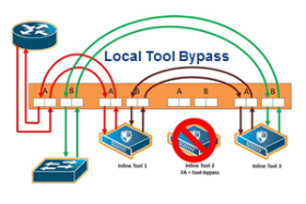
| 6 | Inline Tool Series Local Tool Bypass Failover Action |
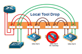
| 7 | Inline Tool Series Local Tool Drop Failover Action |
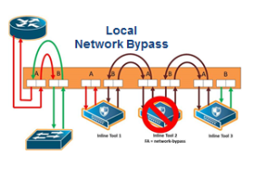
| 8 | Inline Tool Series Local Network Bypass Failover Action |
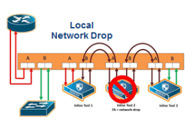
| 9 | Inline Tool Series Local Network Drop Failover Action |
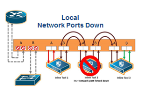
| 10 | Inline Tool Series Local Network Ports Forced Down Failover Action |
11 shows the failure of two individual inline tools in a series with different configured failover actions.
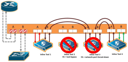
| 11 | Inline Tool Series Local Failover of Two Tools |
Inline Tool Series Per-Direction Order
One of the parameters of inline tool series is the per-direction order of the inline tool series. This parameter configures the traffic direction order of side B traffic with respect to the inline tool list, that is, the direction of the return traffic.
The Return Direction options on the Inline Serial Tool Group page specify the per-direction order of the side B traffic of the inline tool series as follows:
| Reverse specifies that the traffic from network B will flow through the inline tool list in reverse order, for example, from the third tool, to the second tool, to the first tool. This specifies the reverse order of inline tools for both directions. |
| Forward specifies that the traffic from network B will flow through the inline tool list in the order it which it is defined, for example, from the first tool, to the second tool, to the third tool. This specifies the same order of inline tools for both directions of traffic. |
The default is Reverse.
12 shows a simplified view of the flow through the tools:
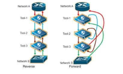
| 12 | Inline Tool Series Per-Direction Order: Simplified Reverse and Forward |
In 12, Reverse is on the left and Forward is on the right. Traffic from network side A to network side B for both reverse and forward flows from the first tool, to the second tool, to the third tool. But traffic from network side B to network side A with reverse, flows from the third tool, to the second tool, to the first tool, whereas traffic from network side B to network side A with forward, flows from the first tool, to the second tool, to the third tool.
13 Inline Tool Series Per-Direction: Reversed shows the reverse direction with the tools connected to the GigaVUE node.
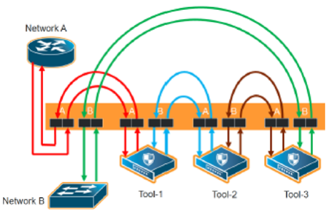
| 13 | Inline Tool Series Per-Direction: Reversed |
13 shows the forward direction with the tools connected to the GigaVUE node.
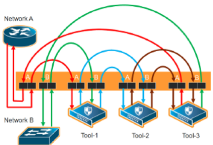
| 14 | Inline Tool Series Per-Direction: Forward |


