Configure Gigamon Resiliency for Inline Protection
Gigamon Resiliency for Inline Protection (GRIP)™ is an inline bypass solution that connects two GigaVUE nodes together so that one node provides high availability to the other node when there is a loss of power. This redundant arrangement of two GigaVUE nodes maintains traffic monitoring by inline tools when one of the nodes is down.
GRIP makes use of the bypass protection switch relays for protected inline networks on GigaVUE‑HC3, GigaVUE‑HC2, and GigaVUE‑HC1 nodes. The following modules are required to provide physical protection:
| bypass combo modules (BPS), for a protected pair of optical inline network ports on GigaVUE‑HC3, GigaVUE‑HC2, or GigaVUE‑HC1 |
| TAP-HC0-G100C0 module, for a protected pair of copper inline network ports on GigaVUE‑HC2 |
| TAP-HC1-G10040 module, for a protected pair of copper inline network ports on GigaVUE‑HC1 |
Note: GRIP is supported on GigaVUE‑HC3 only when there are other modules installed in the node that can provide the stack link. The GRIP solution synchronizes the nodes through a signaling link using a stack link between two stack ports. The BPS-HC3-C25F2G module does not support stack ports, so another module such as PRT-HC3-C08Q08 or SMT-HC3-C05 must be available to be used for that purpose.
In the GRIP solution, two GigaVUE nodes are cabled so that traffic is guided through one GigaVUE node, acting in the primary role, while the other GigaVUE node is on standby, acting in a secondary role. If the primary node fails, the bypass protection switch relays on the modules switch the traffic over from the primary node to the secondary node.
Using the physical protection for either copper or fiber, traffic is guided through inline tools by one of the GigaVUE nodes. The GigaVUE node with the open bypass protection switch relays is the one through which traffic flows. The traffic only flows through one GigaVUE node or the other.
To configure the GRIP solution for copper, use two TAP-HC0-G100C0 modules on GigaVUE‑HC2 or two TAP-HC1-G10040 modules on GigaVUE‑HC1. The capacity will be 1Gb.
To configure the GRIP solution for fiber, use the following:
| two BPS-HC0-D25A4G, BPS-HC0-D25B4G, or BPS-HC0-D35C4G modules on GigaVUE‑HC2. The capacity will be 10Gb. |
| two BPS-HC1-D25A24 modules on GigaVUE‑HC1. The capacity will be 10Gb. |
| two BPS-HC0-Q25A28 modules on GigaVUE‑HC2. The capacity will be 40Gb. |
| two BPS-HC3-C25F2G modules on GigaVUE‑HC3. The capacity will be either 100Gb or 40Gb, depending on the configured port speed of the inline network port pairs. |
Between the two GigaVUE nodes, a 10Gb fiber signaling link is cabled using stack ports. Also, two inline tools are needed for the GRIP solution.
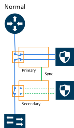
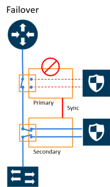
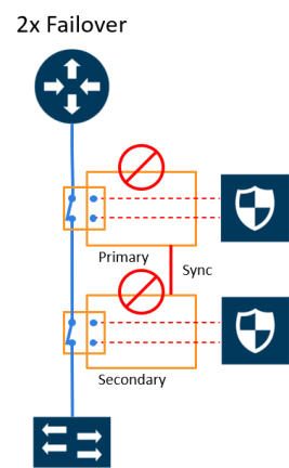
Refer to Figure 1 Traffic Flows Through Node with Primary Role, Figure 2 Traffic Flows Through Node with Secondary Role after Primary is Lost, and Figure 3 Both Nodes Fail; No Traffic Monitoring.
Figure 1 Traffic Flows Through Node with Primary Role shows traffic coming from a network (for example, the Internet) through an edge router at the top of the figure. Two GigaVUE nodes with an inline monitoring tool attached to each node are shown in the middle of the figure. Traffic to end devices on a private network are shown at the bottom of the figure.
The GigaVUE node on the left of the figure is acting in the primary role, while the GigaVUE node on the right is acting in the secondary role. The nodes are synchronized through a signaling link using a stack link between two stack ports.
As shown in Figure 1, traffic only flows through the node with the primary role. On the primary node, the bypass protection switch relays are open. Traffic is directed to the inline tool attached to the primary node. The node with the secondary role watches the state of the signaling link. If the primary node is up, the link is up, and the secondary node takes no action. The bypass protection switch relays on the secondary node are in a closed state. In Figure 1 Traffic Flows Through Node with Primary Role, the dotted lines depict the inactive traffic path.

| Figure 96 | Traffic Flows Through Node with Primary Role |
In Figure 2 Traffic Flows Through Node with Secondary Role after Primary is Lost, power is lost to the GigaVUE node in the primary role. The bypass protection switch relays on the primary node close automatically when the node is down. The secondary node receives a signal through the signaling link that the primary node is down. The secondary node opens its bypass protection switch relays. Now traffic flows through the secondary node and traffic is directed to the inline tool attached to the secondary node.

| Figure 97 | Traffic Flows Through Node with Secondary Role after Primary is Lost |
In Figure 3 Both Nodes Fail; No Traffic Monitoring, both nodes have lost power. The bypass protection switch relays are closed on both GigaVUE nodes. Traffic flows between the networks, but without going through the inline tools, which are both bypassed.

| Figure 98 | Both Nodes Fail; No Traffic Monitoring |
How to Handle Recovery
In the scenario in Figure 2, after traffic is flowing through the secondary node, at some point the primary node will come back up. The primary node will establish the configured inline traffic paths, bring the signaling link up, and open its relays. Traffic will then flow through the primary node again.
Both Nodes Go Down and Only Secondary Comes Up
In the GRIP solution, if both primary and secondary nodes are powered down or if there is a power outage causing both primary and secondary nodes to go down, powering up the secondary alone without the primary ever coming up will cause network traffic to be bypassed instead of being sent to inline tools.
It is not recommended to power up/recover only the secondary node without the primary. The recommendation is to eventually bring the primary up also.
If the primary node is prone to failures or frequent power outages, another recommendation is to change the role of the secondary node to the primary.
How to Cable GigaVUE Nodes
To cable two GigaVUE nodes, as shown in Figure 1 with the primary on the left and the secondary on the right:
| Connect the network shown at the top of Figure 1 to inline network port A on the primary node. |
| Connect inline network port B on the primary node to inline network port A on the secondary node. |
| Connect inline network port B on the secondary node to the network shown at the bottom of the Figure 1. |
| Connect the signaling port on the primary node to the signaling port on the secondary node. |
Configure Software
To configure the GRIP solution in software, first specify a name for a redundancy profile by selecting Inline Bypass > Redundancies, and then clicking New.
The redundancy profile specifies the following:
| Signaling Port—specifies the ports used to signal the state of the two GigaVUE nodes to each other. The ports provide the mechanism to detect loss of power in one of the GigaVUE nodes. |
| Protection Role—specifies the role of the GigaVUE node, as primary, secondary, or suspended. The default is suspended. When suspended, the protection role is on hold. Changing a GigaVUE node from the primary role to the suspended role can be used to manually force the primary node down so the secondary node can become active. The suspended role is also used when performing maintenance. Refer to Limitation for Suspended Role and How to Use Suspended Role for Maintenance. |
The link between the signaling ports on the two GigaVUE-HC nodes is for synchronization. When the node acting in the primary role is up, the signaling link is up, and the node acting in the secondary role sees the link as up. When the primary node loses power, the signaling link is brought down, and the secondary node sees the link as down and takes over.
The redundancy profile combines the protection role with the signaling port. The same redundancy profile is applied to the inline networks, so they have the same properties. If multiple inline networks on each GigaVUE node share the signaling link, they must be configured with the same protection role.
The primary and secondary roles on the two GigaVUE nodes do not change. That is, the role of the primary node stays the same and the role of the secondary node stays the same. The secondary always watches the state of the signaling port for whether the link is up or down.
For example, in Figure 2 Traffic Flows Through Node with Secondary Role after Primary is Lost, after the primary node recovers, it will open its bypass protection switch relays. Through the signaling port, the primary node will indicate that it is ready to receive traffic by setting the link state to up. The secondary node will notice that the link is up and will close its bypass protection switch relays. After recovery, the primary node automatically goes back into service.
Limitation for Suspended Role
Though GRIP is supported in a cluster, there is a limitation when the suspended protection role is used on the standby node in the cluster. The recommendation is to either switch the standby to the leader leader in clustering node relationship (formerly master) or apply the suspended role in the redundancy profile to the leader.
Configure Synchronization
You must synchronize the configuration of the two GigaVUE nodes involved in the GRIP solution. The configuration items that must be synchronized are as follows:
| the signaling ports, as dictated by the signaling link cabling |
| the inline networks, as dictated by the network path cabling between the two GigaVUE nodes |
| the redundancy profiles. The redundancy profile of each GigaVUE nodes needs to have the same signaling port as well as a redundancy role that is compatible with the redundancy role on the other GigaVUE node. For example, one is configured with the primary role and one is configured with the secondary role. |
| the inline tools |
| the inline maps |
For a configuration example of two GigaVUE‑HC2 nodes, refer to Example 4: Gigamon Resiliency for Inline Protection. In the example, the configuration is the same on both nodes, except for the protection role (primary or secondary).
Display Redundancy Control State
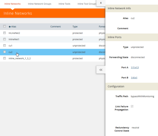
To display the Redundancy Control State, go to the Inline Networks page and click on the alias of the Inline Network for which you want to display the redundancy control state. The state is displayed on the Quick View under Configuration.

| Figure 99 | Redundancy Control State for Inline Network |
Table 1: Redundancy Control States describes each
|
State |
Description |
|
Neutral |
No redundancy profile is configured. |
|
Suspended |
The protection role is configured as suspended. |
|
Primary Forwarding |
The protection role is configured as primary. The node is acting in the primary role. Traffic flows through this node. |
|
Secondary Bypass |
The protection role is configured as secondary. The node is acting in the secondary role. Traffic bypasses this node. |
|
Secondary Forwarding |
The protection role is configured as secondary. The node is acting in the primary role due to a loss of power on the primary node. Traffic flows through this node. |
redundancy control state.
How to Use Suspended Role for Maintenance
Use the suspended protection role to perform maintenance activities on the primary and secondary nodes. Maintenance activities include: bringing up a module, shutting down a module, or swapping a module.
For example, to remove a module on one of the GigaVUE‑HC2 nodes, use the following steps on that module:
| 1. | Select Inline Bypass > Redundancies. |
| 2. | On the Redundancies page, select the redundancy profile, and then click Edit. |
| 3. | For Protection Role, select suspended, and then click Save. |
GRIP for Mixed Topologies
GRIP supports mixed topologies. The two nodes in the GRIP configuration do not both have to be the same GigaVUE HC Series nodes. For example, one node can be a GigaVUE‑HC1 and the other node can be a GigaVUE‑HC2. However the port speed on both nodes (10Gb) must match. In the current software version, GigaVUE‑HC3 is not supported in a mixed topology with either GigaVUE‑HC1 or GigaVUE‑HC2.


