Example 4: Gigamon Resiliency for Inline Protection
Example 5 is an inline bypass solution for GRIP using TAP-HC0-G100C0 modules on the GigaVUE‑HC2, with copper ports.
First, configure the GigaVUE‑HC2 with the primary role, then configure the GigaVUE‑HC2 with the secondary role. The configuration is the same (is synchronized) on both nodes, except for step 3, in which the protection role (primary or secondary) is specified.
Note that in this example, link fail propagation (LFP) is disabled to reduce inline network recovery time after failover. When a primary to secondary failover occurs and LFP is enabled for copper inline bypass links, network service recovery may take several seconds because of Ethernet link renegotiation. Optical links failover faster and typically recover service much faster. For inline networks where only one path is available, this is a consideration. When GRIP is deployed with high availability networks where a second path is present, it is a best practice to leave LFP enabled.
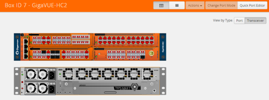
You can use the Chassis page to view the chassis and modules.
Configure Primary Role GigaVUE‑HC2
|
Task
|
Description
|
UI Steps
|
|
|
Configure ports on the TAP-HC0-G100C0 module as passive (in passive mode, relays are closed). Also configure ports, port type (inline-network).
|
|
1.
|
From the left navigation pane, go to System > Ports > Ports > All Ports. |
|
1.
|
Select a port of the TAP-HC0-G100C0 module. |
|
2.
|
Click to open the Ports page. |
|
3.
|
Select Passive for TapTX |
|
5.
|
Repeat steps 2 through 6 for each port on the TAP-HC0-G100C0 module |
|
6.
|
Configure Inline Network ports |
a. Select the port.
b. Click Quick Port Editor.
|
g.
|
Select Inline Network for Type. |
Note: You can use the Chassis page to locate the position of the module in the chassis and identify port IDs.
|
|
|
Configure stack port (for signaling port/link) and enable it.
|
|
1.
|
Select the port and click Edit. |
|
8.
|
Select Enable for Admin. |
|
9.
|
Select Stack for Type. |
|
|
|
Create the redundancy profile by giving it a name and configuring parameters for the redundancy profile such as the signaling port and protection role (primary).
|
|
1.
|
Select Inline Bypass > Redundancies |
|
12.
|
Enter a name for the profile in the Alias field. For example, RP_001. |
|
13.
|
Click in the Signaling Port field and select the stack port configured in Task 2. |
|
14.
|
Select Primary for Protection Role. |
|
|
|
Configure inline network.
This step associates the redundancy profile to the inline network and also disables link fail propagation on the inline network.
|
|
1.
|
Select Inline Bypass > Inline Tools. |
|
17.
|
Enter a name for the inline network in the Alias field. For example, IN_001. |
|
18.
|
Click in the Port A field and select inline network port for network A. |
|
19.
|
Click in the Port B field and select an inline network port f. |
|
20.
|
Select Bypass for Traffic Path. (This is the default setting.) |
|
21.
|
Make sure Link Failure Propagation option is NOT checked. (It is enabled by default.) |
|
22.
|
Click in the Redundancy Profile field and select the profile created in step 3. For example RP_001. |
|
|
|
Configure inline tool ports, port type (inline-tool), and administratively enable them.
|
|
1.
|
From the left navigation pane, go to System > Ports > Ports > All Ports. |
|
23.
|
Select the first port (for example, 1/4/x1) to configure as an inline-tool port. |
|
24.
|
Click Quick Port Editor. |
|
25.
|
Select Inline Network for Type and select Enable for Admin. |
|
27.
|
Select the second port (for example, 1/4/x2) and repeat steps 3 through 5. |
|
|
|
Configure inline tool and failover action. then enable inline tool.
|
|
1.
|
Select Inline Bypass > Inline Tools |
|
28.
|
Enter a name for the inline tool in the Alias field. For example, IT_001 |
|
29.
|
Click in the Port A field and select the first inline tool port configured in Task 5. |
|
30.
|
Click in the Port B field and select the second inline tool port configured in Task 5. |
|
31.
|
Make sure Enable is selected. (It is enabled by default |
|
32.
|
Select NetworkBypass for Failtover action. |
|
|
|
Configure map passall, from inline network to inline tool.
Note: When you delete a map on the primary node, irrespective of the inline-network traffic-path, the traffic is switched to the secondary node. The port utilization must be 0% on the primary node and active on the secondary node.
|
|
1.
|
Select Maps > Maps > Maps. |
|
3.
|
Enter a name for the map in the Alias field. For example, INtoIT. |
|
4.
|
Select Regular for Type. |
|
5.
|
Select Pass All for Subtype. |
|
6.
|
Select the inline network created in Task 4 for Source. For example, IN_001. |
|
7.
|
Select the inline tool created in Task 6. For example, IT_001. |
|
Configure Secondary Role GigaVUE‑HC2
|
Task
|
Description
|
UI Steps
|
|
|
Configure ports on the TAP-HC0-G100C0 module as passive (in passive mode, relays are closed). Also configure ports, port type (inline-network).
|
|
1.
|
From the left navigation pane, go to System > Ports > Ports> All Ports. |
|
8.
|
Select a port of the TAP-HC0-G100C0 module. |
|
9.
|
Click to open the Ports page. |
|
10.
|
Select Passive for TapTX |
|
12.
|
Repeat steps 2 through 6 for each port on the TAP-HC0-G100C0 module |
|
13.
|
Configure Inline Network ports |
a. Select the port.
b. Click Quick Port Editor.
|
n.
|
Select Inline Network for Type. |
Note: You can use the Chassis page to locate the position of the module of the module in the chassis and identify port IDs
|
|
|
Configure stack port (for signaling port/link) and enable it.
|
|
1.
|
Select the port and click Edit. |
|
15.
|
Select Enable for Admin. |
|
16.
|
Select Stack for Type. |
|
|
|
Create the redundancy profile by giving it a name and configuring parameters for the redundancy profile such as the signaling port and protection role (secondary).
|
|
1.
|
Select Inline Bypass > Redundancies |
|
19.
|
Enter a name for the profile in the Alias field. For example, RP_001. |
|
20.
|
Click in the Signaling Port field and select the stack port configured in Task 2. |
|
21.
|
Select Secondary for Protection Role. |
|
|
|
Configure inline network.
This step associates the redundancy profile to the inline network and also disables link fail propagation on the inline network.
|
|
1.
|
Select Inline Bypass > Inline Tools. |
|
24.
|
Enter a name for the inline network in the Alias field. For example, IN_001. |
|
25.
|
Click in the Port A field and select inline network port for network A. |
|
26.
|
Click in the Port B field and select an inline network port f. |
|
27.
|
Select Bypass for Traffic Path. (This is the default setting.) |
|
28.
|
Make sure Link Failure Propagation option is not checked. (It is enabled by default.) |
|
29.
|
Click in the Redundancy Profile field and select the profile created in step 3. For example RP_001. |
|
|
|
Configure inline tool ports, port type (inline-tool), and administratively enable them.
|
|
1.
|
From the left navigation pane, go to System > Ports > Ports > All Ports. |
|
30.
|
Select the first port (for example, 1/4/x1) to configure as an inline-tool port. |
|
31.
|
Click Quick Port Editor. |
|
32.
|
Select Inline Network for Type and select Enable for Admin. |
|
34.
|
Select the second port (for example, 1/4/x2) and repeat steps 3 through 5. |
|
|
|
Configure inline tool and failover action. then enable inline tool.
|
|
1.
|
Select Inline Bypass > Inline Tools |
|
35.
|
Enter a name for the inline tool in the Alias field. For example, IT_001 |
|
36.
|
Click in the Port A field and select the first inline tool port configured in Task 5. |
|
37.
|
Click in the Port B field and select the second inline tool port configured in Task 5. |
|
38.
|
Make sure Enable is selected. (It is enabled by default |
|
39.
|
Select NetworkBypass for Failtover action. |
|
|
|
Configure map passall, from inline network to inline tool.
|
|
1.
|
Select Maps > Maps > Maps. |
|
42.
|
Enter a name for the map in the Alias field. For example, INtoIT. |
|
43.
|
Select Regular for Type. |
|
44.
|
Select Pass All for Subtype. |
|
45.
|
Select the inline network created in Task 4 for Source. For example, IN_001. |
|
46.
|
Select the inline tool created in Task 6. For example, IT_001. |
|
|
|
Configure the path of the traffic to the inline tool, disabling physical bypass on the inline network to open the relay on the node with the primary role.
|
|
1.
|
Select Inline Bypas > Inline Networks. |
|
47.
|
Select the Inline Network configured in Task 4 and click Edit. |
|
48.
|
Select To Inline Tool for Traffic Path |
|
49.
|
Make sure Physical Bypass is NOT checked. |
|


