GigaSMART GTP Correlation
Required License: GTP Filtering & Correlation
The GigaSMART GTP application correlates traffic based on mobile subscriber IDs in the packet data networks of service providers. It provides a mechanism to filter and forward session traffic for subscribers to tools. GTP correlation assists mobile carriers in debugging and analyzing GTP traffic in their 3G/4G networks.
GPRS Tunneling Protocol (GTP) is an IP/UDP-based protocol that carries mobile data across service provider networks. The protocol is used in General Packet Radio Service (GPRS) networks such as: Global System for Mobile Communications (GSM), Universal Mobile Telecommunications System (UMTS), and Long Term Evolution (LTE). The protocol encapsulates user data that passes through the core network and carries subscriber-specific signaling traffic.
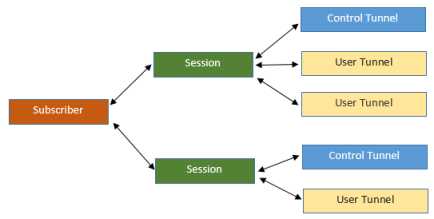
GTP includes both control plane (GTP-c) and user-data plane (GTP-u) traffic. To gain an accurate view into the subscriber’s session, GTP tunnels are used to correlate the subscriber-specific control plane and user-data plane traffic. A GTP session is the minimum unit of GTP correlation consisting of one control and multiple user tunnels. All GTP traffic belonging to the same session is forwarded to the same tool port.
Using GTP correlation, you can filter, replicate, and forward specific subscriber sessions to specific tools by correlating the subscriber IDs that are exchanged as part of the control sessions to the corresponding tunnel IDs (TEIDs) that are part of the user-data plane traffic.
GTP correlation provides the following:
|
•
|
stateful filtering based on subscriber IDs (IMSI, IMEI, and MSISDN) |
|
•
|
stateful filtering based on GTP version or EPC interface |
|
•
|
stateful correlation of GTP-c with GTP-u traffic |
|
•
|
correlation of subscriber ID with corresponding tunnel ID |
|
•
|
forwarding of the subscriber-specific control and user-data plane traffic to a tool or group of tools |
|
•
|
supports a maximum of 5 million GTP subscriber sessions for GigaVUE-HC2 nodes, whereas, it supports 12 million GTP subscriber sessions for GigaVUE-HC3 nodes |
Starting in software version 4.5, a GigaSMART group (gsgroup) associated with GTP applications can have multiple GigaSMART engine port members (e ports), up to four, forming an engine group. Refer to GTP Scaling.
Filtering on Subscriber IDs and Version
GTP stateful filtering supports filtering of GTP sessions based on the following subscriber IDs:
|
Component
|
Description
|
|
imsi
|
The International Mobile Subscriber Identity (IMSI) is a number that identifies a subscriber of a cellular network. It is a unique identification associated with all cellular networks.
An IMSI is usually a 15 digit number, associated with GSM, UMTS, and LTE network mobile phone users.
|
|
imei
|
The International Mobile Station Equipment Identity (IMEI) is a number, usually unique, that identifies 3rd Generation Partnership Project (3GPP), for example, GPRS, LTE, as well as Integrated Digital Enhanced Network (iDEN) mobile phones, and some satellite phones.
The IMEI identifies the device, but has no permanent relationship to the subscriber. Instead, the subscriber is identified by transmission of an IMSI number, stored on a SIM card.
|
|
msisdn
|
The Mobile Station International Subscriber Directory Number (MSISDN) is a unique number that identifies subscribers in a GSM or UMTS mobile network. This numbering plan is defined in the ITU-T recommendation E.164. The maximum length of an MSISDN is 15 digits.
|
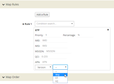
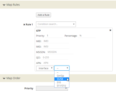
In addition to filtering on subscriber IDs, you can optionally filter on GTP version (v1 or v2) or Evolved Packet Core (EPC) interface. Filtering on the EPC interface allows traffic to be segmented for a given interface.
The supported interfaces for EPC filtering are as follows:
When filtering on EPC interface, you do not also need to specify version, as the version is implied.
To create maps using GTP, specify a Second Level Flow Sample map and select GTP for the rule. When adding a map rule, you can specify the following:
|
•
|
subscriber IDs (IMSI, IMEI, or MSISDN) |
|
•
|
number of digits. The maximum number of digits for the IMSI or MSISDN value is 15. The maximum number of digits for the IMEI value is 16. To specify the prefix for IMSI, IMEI, or MSISDN, you can use a wild card character or a digit string followed by a wild card character. |
|
•
|
map comment to label the purpose of a rule or the type of traffic covered by a rule |
Note: In a map, version and EPC interface cannot be specified in the same flowrule, but they can be specified in different flowrules.
Note: The maximum number of GTP flowrules is 32 per map.
For examples of filtering on GTP version, refer to Configure GTP Correlation Examples.
|
Figure 4
|
GTP EPC Interface |
Session Correlation
Each GTP session has one control tunnel and one or more user tunnels. All the tunnels are correlated together into a session. Packets belonging to the same session will be forwarded to the same tool port. Refer to the following figure.
In a second level map, the following can be specified:
|
•
|
one tool port—packets from one subscriber (same subscriber ID), from one or more GTP sessions, will be forwarded to the same tool port. |
|
•
|
multiple tool ports—packets from one subscriber (same subscriber ID), from multiple GTP sessions will be correlated and forwarded to same tool port. Using load balancing, GTP traffic that matches the same map but belongs to different subscribers can be load balanced to multiple tool ports. |
Supported Interfaces
GTP is used at multiple interfaces by multiple devices in the core network. GTP stateful correlation is implemented for the following interfaces:
|
•
|
Gn/Gp (for GPRS). The Gn interface is between SGSN-GGSN only. |
|
•
|
S1-U, S11U and S11 (for LTE) |
Support for interfaces for both GPRS and LTE networks includes the handovers between the different networks. Refer to the following figure.
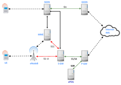
For LTE networks, the following GTP traffic will be correlated to the specific mobile subscriber and routed to the same tool port:
|
•
|
GTP-c traffic on the S11 interface between MME and S-GW |
|
•
|
GTP-u traffic on the S11u interface between MME and S-GW |
|
•
|
GTP-u traffic on the S1u interface between eNodeB and S-GW |
|
•
|
GTP-c traffic on the S10 interface between MMEs |
|
•
|
GTP-c traffic on the S5/S8 interface between S-GW and P-GW |
|
•
|
GTP-u traffic on the S5u interface between S-GW and P-GW |
|
•
|
GTP-c traffic on the S2b interface between P-GW and ePDG |
|
•
|
GTP-u traffic on the S2b-U interface between P-GW and ePDG |
In order to correlate GTP-c and GTP-u traffic running on different interfaces, you must tap into the correct interfaces, as follows:
|
•
|
Gn/Gp—one interface runs both GTP-c and GTP-u |
|
•
|
S5/S8—one interface runs both GTP-c and GTP-u |
|
•
|
S1u, S11u, and S11—these three interfaces have to be tapped at the same time to get both GTP-c and GTP-u to perform the correct correlation. |
|
•
|
S2b-C and S2b-U interfaces needs to be tapped to get GTP-c and GTP-u traffic for correlation. |
For examples of filtering on GTP interface types Gn/Gp, S5/S8, S1 and S11, refer to Configure GTP Correlation Examples.
Conditional S10 Support
The following table outlines support for the S10 interface. In the table, No means not supported, Conditional means there is limited support of the S10 interface.
|
S10
|
Support
|
|
Forward Relocation Request/Resp
|
Conditional; IMSI must be present in Forward Relocation Request
|
|
Forward Relocation Complete Notification/Ack
|
Conditional; IMSI must be present in Forward
Relocation Request for Forward Relocation Complete Notification/Ack to be supported
|
|
Context Request/Response and Ac
|
Conditional; IMSI must be present
|
|
Identification Request/Response
|
No
|
|
Forward Access Context Notification/Ack
|
No
|
|
Relocation Cancel Request/Response
|
No
|
|
Configuration Transfer Tunnel
|
No
|
GigaSMART 3GPP CUPS Support
CUPS stands for Control and User Plane Separation of Evolved Packet Core nodes. 3GPP CUPS enhances the Evolved Packet Core nodes by introducing the following three new interfaces between the control plane and user plane functions of the S-GW, P-GW and TDF, respectively:
Figure 3: 3GPP CUPS Network topology illustrates 3GPP CUPS Network topology
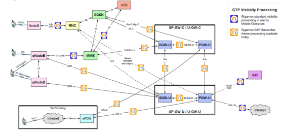
|
Figure 5
|
3GPP CUPS Network topology |
The advantages of 3GPP CUPS include the following:
|
•
|
Increased flow of data traffic. |
|
•
|
Independent User Plane and Control Plane scaling. |
Starting in software version 5.6, GigaSMART GTP correlation leverages the SXa and SXb interfaces of the 3GPP CUPS architecture to receive additional traffic that is used to include the GTP session with the Packet Forwarding Control Protocol (PFCP) session. With this enhancement, control traffic and user traffic are processed at the following nodes (engines):
|
•
|
Control Processing Node (CPN) - to process control traffic |
|
•
|
User Processing Node (UPN) - to process user traffic |
The CPN and UPN communicate with each other.
The following topology diagram explains about the communication between CPN and UPN:
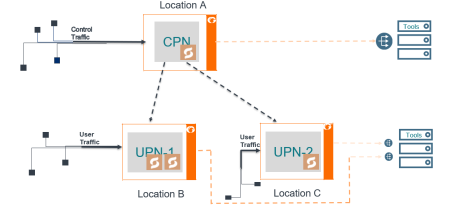
|
Figure 6
|
Topology diagram of CPN and UPN Connections |
The user traffic is processed in UPN-1 and UPN-2 present in Location B and Location C, respectively. The control traffic is processed at CPN present in Location A, and few control parameters are sent to UPN-1 and UPN-2. Location A handles control traffic corresponding to the user traffic of Location B and Location C. The CPN and UPN can be present at the same location or at a different location.
When the GigaSMART engine in the CPN receives the control traffic, it generates a session table with information such as IMSI, MSISDN, IMEI, QCI, APN values and performs whitelisting, flow sampling and load balancing. UPN supports engine grouping, whereas CPN do not support engine grouping.
A Subscriber Flow Forwarding Protocol (SFFP) profile is created from CPN IP interface to transfer the appropriate control parameters to the corresponding UPN IP interface. The apps exporter at the CPN IP interface instructs the control processing node about the number of user groups it supports, and the source and destination port to route the packets.
The apps listener at the UPN IP interface receives the control parameters from the CPN to UPN interface and helps the UPN to generate a session table based on the Transport Agent (TA) packet information received at the IP interface. IP interface is a communication channel between the CPN and the UPN. The session table performs whitelisting, flow sampling and load balancing at the UPN. UPN correlates the user traffic by using the populated session table.
Limitations
|
•
|
Engine Grouping on CPN is not suported. |
|
•
|
SXa, SXb packets are broadcasted to all the tool ports. |
|
•
|
A loop back IP connection with a router is required in-between the CPN and UPN if they are present within the same chassis. |
The following table summarizes the required tasks for configuring the GigaSMART 3GPP CUPS:
|
S.No
|
Task
|
Refer to...
|
|
1.
|
Configure an IP interface to send and receive the Gigamon Transport Agent packets.
|
IP Interfaces
|
|
2
|
Configure the apps listener to configure the TCP connection at the IP interface in the UPN.
|
Configure Apps Listener
|
|
3
|
Configure the apps exporter to configure the TCP connection at the IP interface in the CPN.
|
Configure Apps Exporter
|
|
4
|
Configure the SFFP Profile.
Note: You can configure SFFP profile using CLI commands and Ansible Playbook.
|
To configure the SFPP proflies refer to the command SFFP profile in GigaVUE-OS-CLI Reference Guide 5.8 and GigaVUE-FM Automation with Ansible Playbook. |
|
5
|
In the first level map configuration create a new rule to pass SXa, SXb packets through port number 8805.
|
|
|
6
|
Configure a node role for the control and user node, and attach a SFFP-profile to the CPN node in the GigaSMART engine.
|
To associate the SFFP profile to the CPN node refer to the command SFFP profile in GigaVUE-OS-CLI Reference Guide 5.8.
|
Configure Apps Listener
To configure the apps listener, do the following:
|
1.
|
Select Physical Nodes from the Navigation pane. |
|
2.
|
Select the device on which you want to configure an apps listener by clicking the Cluster ID of the device. |
|
3.
|
Select GigaSMART > TCP/IP Host > Listener. |
|
5.
|
On the Listener page, do the following: |
|
a.
|
In the Alias field, enter the name of the listener. |
|
b.
|
In the Application Type, select GTP CUPS from the drop down list. |
|
c.
|
In the GigaSMART Group, select a GigaSMART group for which you want to associate the Listener. |
|
d.
|
In the L3 Protocol drop down list, select a Layer 3 protocol. |
|
e.
|
In the L4 Protocol drop down list, select a Layer 4 protocol. |
|
f.
|
In the L4 Port field, enter a list of port numbers through which the traffic is to be received. The value must be between 1 and 65535. |
|
g.
|
In the TTL field, enter the time-to-live (TTL) value. The value must be between 1 and 255. |
|
h.
|
In the DSCP field, enter the DSCP value. The value must be between 0 and 63. |
To view the Apps Listener statistics, go to GigaSMART > TCP/IP Host > Listener Statistics.
Configure Apps Exporter
To configure the apps exporter, do the following:
|
1.
|
Select Physical Nodes from the Navigation pane. |
|
2.
|
Select the device on which you want to configure a SFFP profile by clicking the Cluster ID of the device. |
|
3.
|
Select GigaSMART > TCP/IP Host > Exporter. |
|
5.
|
On the Exporter page, do the following: |
|
a.
|
In the Alias field, enter the name of the exporter. |
|
b.
|
In the Application Type, select GTP CUPS from the drop down list. |
|
c.
|
In the GigaSMART Group, select a GigaSMART group for which you want to associate the Exporter. |
|
d.
|
In the Source field do the following: |
|
•
|
Select an IP interface through which you want to export the information from CPN. |
|
•
|
In the L4 Port, enter the port number through which the traffic is to be transferred. The value must be between 1 and 65535. |
|
6.
|
In the Destination field do the following: |
|
•
|
Select a Layer 3 Protocol. |
|
•
|
Enter the time-to-live (TTL) value. The value must be between 1 and 255. |
|
•
|
Enter the DSCP value. The value must be between 0 and 63. |
|
•
|
Select a Layer 4 Protocol and enter their corresponding port value. The L4 port value must be between 1 and 65535. |
To view the Apps Exporter statistics, go to GigaSMART > TCP/IP Host > App Exporter.
Stand-Alone User Processing Node Traffic Monitoring
In Stand-alone User Processing Node (UPN) traffic monitoring, the UPN processes the subscriber information that is extracted from the PFCP packets and correlates with the GTP-u traffic without the CPN. When the traffic contains the User's field information such as IMSI, IMEI, you can use the Stand-Alone User Processing Node traffic monitoring.

What is PFCP?
PFCP (Packet Forwarding Control Protocol) is a 3GPP Protocol that is communicated on the Sx/N4 Interface between the Control Plane (CP) elements and User Plane (UP) elements. The CP element programs the UP element with policies on how to forward packets. PFCP packets convey information in the form of Information Elements (IE). PFCP allows an optional IE called User Fields that contains IMSI/SUPI, IMEI/PEI, MSISDN/GPSI information of the Subscriber during PFCP Session Establishment Request.
The UPN performs the following activities in the Stand-alone mode:
- Processes the PFCP session establishment request and extracts the IMSI, User IP and TEID for both end points. The information in the PFCP traffic is used to populate the UPN's session table.
- Creates a GTP control tunnel based on the subscriber information and corresponding user tunnel. GTP-U look up is correlated based on the IP TEID .
The following diagrams explain the functioning of UPN in Stand-alone mode:
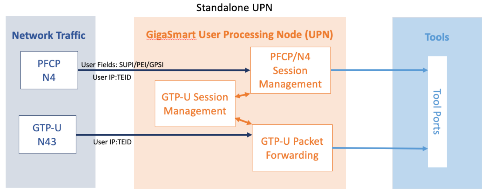
Rules and Notes
- A Stand-alone UPN traffic monitoring session can be created only when there is atleast SUPI in the user fields.
- You cannot perform RAN correlation or Network Slicing Correlation in Stand alone UPN traffic monitoring
- UPN does not receive SFFP messages in the User field parse mode.
Configure Stand-Alone User Processing Node Traffic Monitoring
To configure Stand-Alone User Processing Node Traffic Monitoring, refer to Configuration of 5G CUPS.
The following are the points to remember while configuring Stand-Alone User Processing Node:
- You must enable the stand-alone mode in UPN while creating the solution in Ansible.
- Once the stand-alone mode is enabled, UPN cannot connect with the CPN, and you cannot the change the mode. To change the mode, you need to delete the UPN from the solution and add a new one.
GTP Session Timeout
To access GigaSMART within GigaVUE-FM, access a device that has been added to GigaVUE-FM from the GigaVUE-FM interface. GigaSMART appears in the navigation pane of the device view on supported devices. Refer to Access GigaSMART from GigaVUE-FM for details.
In prior software versions, the complete GTP session timeout was eight hours. Starting with software version 4.2, the GTP session timeout is configurable, with eight hours as the default.
To configure the GTP session timeout, do the following:
|
1.
|
From the device view, select GigaSMART > GigaSMART Groups > GigaSMART Groups. |
|
2.
|
Click New to create a new GigaSMART Group or Edit to modify an existing one. |
|
3.
|
Under GigaSMART Parameters, go to GTP Flow. |
|
4.
|
Enter the timeout in the Timeout field. The following figure shows an example where the timeout value is set to 60. |

The GTP session timeout disconnects a GTP session if it has been inactive for the timeout value. The timeout can be configured as an integer from 1 to 6000, in increments of 10 minutes. The default value is 48, which is 480 minutes, which is 8 hours.
Priorities for Flow Rules and Maps
One virtual port can have multiple maps, and for each map, you can add multiple flow rules with different filtering attributes. The priorities for flow rules are as follows:
|
•
|
a rule with a drop action has a higher priority than a rule with a pass action |
|
•
|
for the same pass or drop action, the priorities are IMSI, IMEI, or MSISDN in descending order |
In a GTP session, if one IMSI, IMEI, or MSISDN rule is matched, the map is matched. For example, if any one of the following matches any rule shown in the following figure, map1 (which is a Second Level Flow Filter map) is matched:
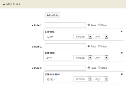
In addition, in one map, all drop rules are matched first and all pass rules are matched next.
For example, in a GTP session, if an IMSI matches the first rule in map1 and an IMEI matches the second rule in map1, because the drop rule has higher priority, the packet will be dropped:
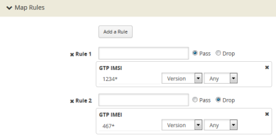
If multiple maps are matched, the map with the highest priority will be considered for further processing. For example, the Figure 5: Rule in Map1 shows the rule for map1 while the rule Figure 1: NetFlow Generation Gigamon Solution shows the rule for map2. In a GTP session, if an IMSI matches the first rule in map1 and an IMEI matches the first rule in map2, because map1 has higher priority, the packet will be passed.


Configure GTP Correlation Examples
The following sections provide examples of GTP correlation and GTP load balancing. Refer to the following examples:
Example 1: Identifying High-Value and/or Roaming Subscribers Based on IMSIs
Use GTP correlation to identify high value subscribers based on an IMSI or group of IMSIs. GTP correlation keeps track of the IMSIs that you are interested in monitoring. It correlates them to the corresponding data/user-plane sessions for the subscriber and/or group of subscribers. Filtering on subscriber ID (IMSI) limits the amount of traffic that is sent to monitoring tools.
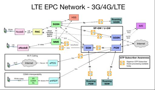
In Example 1, filter rules are configured to identify and forward all the traffic related to subscribers identified by an IMSI prefix. All traffic specific to the filtered IMSIs 22222222222223*, including GTP-c and GTP-u, is forwarded to a monitoring tool. A shared collector is configured to which traffic not matching the filters is sent.
To access GigaSMART within GigaVUE-FM, access a device that has been added to GigaVUE-FM from the GigaVUE-FM interface. GigaSMART appears in the navigation pane of the device view on supported devices. Refer to Access GigaSMART from GigaVUE-FM for details.
|
Task
|
Description
|
UI Steps
|
|
1
|
Configure one network and two tool type of ports.
|
|
1.
|
Select Ports > Ports > All Ports. |
|
2.
|
Click Quick Port Editor. |
|
3.
|
In the Quick View Editor set one port to Network and two ports to Tool. |
|
4.
|
Select Enable on each port. |
|
6.
|
Close the Quick Port Editor. |
|
|
2
|
Configure a GigaSMART group and associate it with a GigaSMART engine port.
|
|
1.
|
From the device view, select GigaSMART > GigaSMART Groups > GigaSMART Groups. |
|
3.
|
Type a name for the GigaSMART Group in the Alias field. |
|
4.
|
Click in the Port List field and select an engine port. |
|
5.
|
Under GTP Flow set the Timeout. The default is value is 48, which is 480 minutes. |
|
|
3
|
Configure the GigaSMART operation and assign it to the GigaSMART group to enable GTP correlation.
|
|
1.
|
From the device view, select GigaSMART > GigaSMART Operations (GSOP > GigaSMART Operation. |
|
2.
|
Type a name for the GigaSMART Group in the Alias field. |
|
3.
|
Click in the GigaSMART Operations (GSOP) field and select Flow Filtering. |
|
|
4
|
Configure a virtual port and assign it to the same GigaSMART group.
|
|
1.
|
From the device view, select GigaSMART > Virtual Ports. |
|
3.
|
Type a name for the virtual port in the Alias field. |
|
4.
|
Click in the GigaSMART Groups field, and select the GigaSMART Group created in Task 2. |
|
|
5
|
Create a first level map that directs GTP traffic from physical network port/s to the virtual port you created in the previous step.
Note: In the rules, 2123 is GTP-c traffic and 2152 is GTP-u traffic.
|
|
1.
|
Select Maps > Maps > Maps |
|
•
|
Select First Level for Type |
|
•
|
Select By Rule for Subtype |
|
•
|
Select a network port for the Source |
|
•
|
Select the virtual port configured int Task 4 for the Destination |
|
c.
|
Select Bi Directional. |
|
e.
|
Set the source to 2123 |
|
e.
|
Set the source to 2153 |
|
c.
|
Select IPv4 Fragmentation |
|
d.
|
Set Value to allFragNoFirst |
|
|
6
|
Create a second level map that takes traffic from the virtual port, applies the GigaSMART operation, matches IMSIs specified by the flow rule, and sends matching traffic to physical tool ports.
|
|
1.
|
Select Maps > Maps > Maps |
|
•
|
Select Second Level for Type |
|
•
|
Select Flow Filter for Subtype |
|
•
|
Select a the virtual port configured in Task for the Source |
|
•
|
Select the a tool port configured in Task 1 for the Destination |
|
•
|
Select the GigaSMART Operation created in Task 3 from the GSOP list. |
|
d.
|
Enter 22222222222223* in the IMSI field. |
|
|
7
|
Add a shared collector for any unmatched data and send it to the second tool port.
|
|
1.
|
Select Maps > Maps > Maps |
|
•
|
Select Second Level for Type |
|
•
|
Select Collector for Subtype |
|
•
|
Select a the virtual port configured in Task for the Source |
|
•
|
Select the second tool port configured in Task 1 for the Destination |
|
|
8
|
Display the configuration for Example 1.
|
To display the configuration for the GigaSMART Group:
|
1.
|
From the device view, select GigaSMART > GigaSMART Groups. |
|
2.
|
Click on the alias for the GigaSMART Group to display the Quick View. |
To display the configuration for the GigaSMART Operation:
|
1.
|
From the device view, select GigaSMART > GigaSMART Operations (GSOP) > GigaSMART Operation. |
|
2.
|
Click on the alias for the GigaSMART Operation to display the Quick View. |
To display the configuration for the maps:
|
1.
|
Select Maps > Maps > Maps. |
|
2.
|
Click on a map alias to display the Quick View for the map. |
|
Display GTP Correlation Flow Ops Report Statistics
To display GTP correlation statistics associated with the GigaSMART group, select GigaSMART > GigaSMART Operations > Statistics.
Refer to Flow Ops Report Statistics Definitions for GTP on page 635 for descriptions of these statistics.
Example 2: Identifying GTP Versions
As part of GTP correlation, GigaVUE nodes also provide the flexibility to identify GTPv1 and GTPv2 messages. GTP version information is typically exchanged only as part of the control sessions. By correlating the control and user-plane sessions, GigaVUE nodes can identify, filter, and forward all sessions specific to a GTPv1 or v2 to one or more monitoring/analytic tools.
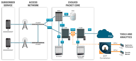
In Example 2, EMEI traffic is distributed based on GTP versions as follows:
|
•
|
Filter and forward GTPv1 to a tool port |
|
•
|
Filter and forward GTPv2 to another tool port |
|
Task
|
Description
|
UI Steps
|
|
1
|
Configure one network and two tool type of ports.
|
|
1.
|
Select Ports > Ports > All Ports. |
|
2.
|
Click Quick Port Editor. |
|
3.
|
In the Quick View Editor set one port to Network and two ports to Tool. |
|
4.
|
Select Enable on each port. |
|
6.
|
Close the Quick Port Editor. |
|
|
2
|
Configure a GigaSMART group and associate it with a GigaSMART engine port.
|
|
1.
|
From the device view, select GigaSMART > GigaSMART Groups > GigaSMART Groups. |
|
3.
|
Type a name for the GigaSMART Group in the Alias field. |
|
4.
|
Click in the Port List field and select an engine port. |
|
5.
|
Under GTP Flow set the Timeout. The default is value is 48, which is 480 minutes. |
|
|
3
|
Configure the GigaSMART operation and assign it to the GigaSMART group to enable GTP correlation.
|
|
1.
|
From the device view, select GigaSMART > GigaSMART Operations > GigaSMART Operation. |
|
2.
|
Type a name for the GigaSMART Group in the Alias field. |
|
3.
|
Click in the GigaSMART Operations (GSOP) field and select Flow Filtering. |
|
|
4
|
Configure a virtual port and assign it to the same GigaSMART group.
|
|
1.
|
From the device view, select GigaSMART > Virtual Ports. |
|
3.
|
Type a name for the virtual port in the Alias field. |
|
4.
|
Click in the GigaSMART Groups field, and select the GigaSMART Group created in Task 2. |
|
|
5
|
Create a first level map that directs GTP traffic from physical network ports to the virtual port you created in the previous task.
Note: In the rules, 2123 is GTP-c traffic and 2152 is GTP-u traffic.
|
|
1.
|
Select Maps > Maps > Maps |
|
•
|
Select First Level for Type |
|
•
|
Select By Rule for Subtype |
|
•
|
Select a network port for the Source |
|
•
|
Select the virtual port configured int Task 4 for the Destination |
|
c.
|
Select Bi Directional. |
|
e.
|
Set the source to 2123 |
|
e.
|
Set the source to 2153 |
|
c.
|
Select IPv4 Fragmentation |
|
d.
|
Set Value to allFragNoFirst |
|
|
6
|
Create a second level map that takes traffic from the virtual port, applies the GigaSMART operation, matches IMEIs specified by the flow rule, and sends matching traffic to a tool port.
|
|
1.
|
Select Maps > Maps > Maps |
|
•
|
Select Second Level for Type |
|
•
|
Select Flow Filter for Subtype |
|
•
|
Select a the virtual port configured in Task for the Source |
|
•
|
Select the a tool port configured in Task 1 for the Destination |
|
•
|
Select the GigaSMART Operation created in Task 3 from the GSOP list. |
|
d.
|
Enter * in the IMSEI field and set Version to V1 |
|
|
7
|
Create a second level map that takes traffic from the virtual port, applies the GigaSMART operation, matches IMEIs specified by the flow rule, and sends matching traffic to another tool port.
|
|
1.
|
Select Maps > Maps > Maps |
|
•
|
Select Second Level for Type |
|
•
|
Select Flow Filter for Subtype |
|
•
|
Select a the virtual port configured in Task for the Source |
|
•
|
Select the second tool port configured in Task 1 for the Destination |
|
•
|
Select the GigaSMART Operation created in Task 3 from the GSOP list. |
|
d.
|
Enter * in the IMSI field and set Version to V2 |
|
|
8
|
Display the configuration for Example 2.
|
To display the configuration for the GigaSMART Group:
|
1.
|
From the device view, select GigaSMART > GigaSMART Groups > Maps. |
|
2.
|
Click on the alias for the GigaSMART Group to display the Quick View. |
To display the configuration for the GigaSMART Group:
|
1.
|
From the device view, select GigaSMART > GigaSMART Operations (GSOP) > GigaSMART Operations |
|
2.
|
Click on the alias for the GigaSMART Operation to display the Quick View. |
To display the configuration for the maps:
|
1.
|
Select Maps > Maps > Maps. |
|
2.
|
Click on the map alias to display the Quick View for the map. |
|
Example 3: Same Subscriber, Filter on Different Versions
In this example, traffic from the same subscriber is forwarded to two different load balancing groups based on version. GTP version 1 traffic is sent to one load balancing group and GTP version 2 traffic is sent to another load balancing group.
|
Task
|
Description
|
UI Steps
|
|
1
|
Configure one network and multiple tool type of ports.
|
|
1.
|
Select Ports > Ports > All Ports. |
|
2.
|
Click Quick Port Editor. |
|
3.
|
In the Quick View Editor set one port to Network and multiple ports to Tool. For example, set 1/2/g1 as a Network port and ports 1/2/g5 through 1/2/g9 as Tool ports. |
|
4.
|
Select Enable on each port. |
|
6.
|
Close the Quick Port Editor. |
|
|
2
|
Configure a GigaSMART group and associate it with a GigaSMART engine port.
|
|
1.
|
From the device view, select GigaSMART > GigaSMART Groups > GigaSMART Groups. |
|
3.
|
Type a name for the GigaSMART Group in the Alias field. |
|
4.
|
Click in the Port List field and select an engine port. |
|
|
3
|
Configure the GigaSMART operation and assign it to the GigaSMART group.
|
|
1.
|
From the device view, select GigaSMART > GigaSMART Operations > GigaSMART Operations. |
|
2.
|
Type a name for the GigaSMART Group in the Alias field. |
|
3.
|
Click in the GigaSMART Operations field and select Flow Filtering. |
|
4.
|
Click in the GigaSMART Operations filed and select Load Balancing. |
|
5.
|
Configure the Load Balancing as follows:. |
|
|
4
|
Configure a virtual port and assign it to the GigaSMART group.
|
|
1.
|
From the device view, select GigaSMART > Virtual Ports. |
|
3.
|
Type a name for the virtual port in the Alias field. |
|
4.
|
Click in the GigaSMART Groups field, and select the GigaSMART Group created in Task 2. |
|
|
5
|
Create two port groups (one for version 1 traffic and one for version 2 traffic) and enable load balancing on the port groups.
|
|
1.
|
Select Ports > Port Groups > All Port Groups. |
|
3.
|
Type a name for the GigaSMART Group in the Alias field. For example, pglbv1. |
|
4.
|
Select SMART Load Balancing to enable load balancing |
|
5.
|
Click in the Ports field and select half the tool ports configured in Task 1. |
|
6.
|
Repeat steps 2 through 4, creating a second port group with the other ports configured in Task 1 |
|
|
6
|
Create an ingress (first level) map.
|
|
1.
|
Select Maps > Maps > Maps. |
|
•
|
Enter an alias. For example, map1_1. |
|
•
|
Select First Level for Type |
|
•
|
Select By Rule for Subtype |
|
•
|
Select a network port for the Source |
|
•
|
Select the virtual port configured in Task 4 for the Destination |
|
4.
|
Click Add a Rule to create a rule. |
|
•
|
Enter a MAC address. For example, 00:a0:d1:e1:02:01 |
|
•
|
Enter a MAC mask. For example, 0000.0000.0000 |
|
|
7
|
Create a second level map.
|
|
1.
|
Select Maps > Maps > Maps. |
|
•
|
Enter an alias. For example, map2_1. |
|
•
|
Select Second Level for Type |
|
•
|
Select Flow Filter for Subtype |
|
•
|
Select the virtual port configured in Task 4 for the Source |
|
•
|
Select the first port group for Destination |
|
•
|
Select the GigaSMART Operation configured in Task 3 from the GSOP list. |
|
4.
|
Click Add a Rule to create a rule. |
|
•
|
Enter * in the IMSI field |
|
|
8
|
Create another second level map.
|
|
1.
|
Select Maps > Maps > Maps. |
|
•
|
Enter an alias. For example, map2_2. |
|
•
|
Select Second Level for Type |
|
•
|
Select Flow Filter for Subtype |
|
•
|
Select the virtual port configured in Task 4 for the Source |
|
•
|
Select the second port group for Destination |
|
•
|
Select the GigaSMART Operation configured in Task 3 from the GSOP list. |
|
4.
|
Click Add a Rule to create a rule. |
|
•
|
Enter * in the IMSI field |
|
Example 4: Same Subscriber, Filter on Different Interfaces
In this example, traffic from the same subscriber is forwarded to two different load balancing groups based on interface. In this example, VLANs 1601 and 1602 are from S5/S8 interface and VLANs 1611 and 1612 are from S11/S1-U interface. The first level maps split the VLAN traffic to different virtual ports. The second level maps send the traffic to different load balancing groups.
|
Task
|
Description
|
UI Steps
|
|
1
|
Configure one network and multiple tool type of ports.
|
|
1.
|
Select Ports > Ports > All Ports. |
|
2.
|
Click Quick Port Editor. |
|
3.
|
In the Quick View Editor set one port to Network and multiple ports to Tool. For example, set 1/2/g1 as a Network port and ports 1/2/g5 through 1/2/g9 as Tool ports. |
|
4.
|
Select Enable on each port. |
|
6.
|
Close the Quick Port Editor. |
|
|
2
|
Configure a GigaSMART group and associate it with a GigaSMART engine port.
|
|
1.
|
From the device view, select GigaSMART > GigaSMART Groups > GigaSMART Groups. |
|
3.
|
Type a name for the GigaSMART Group in the Alias field. |
|
4.
|
Click in the Port List field and select an engine port. |
|
|
3
|
Configure the GigaSMART operation and assign it to the GigaSMART group.
|
|
1.
|
From the device view, select GigaSMART > GigaSMART Operations > GigaSMART Operations. |
|
2.
|
Type a name for the GigaSMART Group in the Alias field. |
|
3.
|
Click in the GigaSMART Operations field and select Flow Filtering. |
|
4.
|
Click in the GigaSMART Operations filed and select Load Balancing. |
|
5.
|
Configure Load Balancing as follows: |
|
|
4
|
Configure virtual ports and associate them with the GigaSMART group.
|
|
1.
|
From the device view, select GigaSMART > Virtual Ports. |
|
3.
|
Type a name for the virtual port in the Alias field. |
|
4.
|
Click in the GigaSMART Groups field, and select the GigaSMART Group created in Task 2. |
|
6.
|
Repeat steps 1 through 5 to create a second virtual port. |
|
|
5
|
Create two port groups (one for version 1 traffic and one for version 2 traffic) and enable load balancing on the port groups.
|
|
1.
|
Select Ports > Port Groups > All Port Groups. |
|
3.
|
Type a name for the GigaSMART Group in the Alias field. For example, pglbv1. |
|
4.
|
Select SMART Load Balancing to enable load balancing |
|
5.
|
Click in the Ports field and select half the tool ports configured in Task 1. |
|
6.
|
Repeat steps 2 through 4, creating a second port group with the other ports configured in Task 1 |
|
|
6
|
Create a first level map.
|
|
1.
|
Select Maps > Maps > Maps. |
|
•
|
Enter an alias. For example, map1_1. |
|
•
|
Select First Level for Type |
|
•
|
Select By Rule for Subtype |
|
•
|
Select a network port for the Source |
|
•
|
Select the first virtual port configured in Task 4 for the Destination |
|
4.
|
Click Add a Rule to create a rule. |
|
•
|
Enter 1601 for the Min value |
|
•
|
Enter 1602 for the Max value |
|
|
7
|
Create another first level map.
|
|
1.
|
Select Maps > Maps > Maps. |
|
•
|
Enter an alias. For example, map1_2. |
|
•
|
Select First Level for Type |
|
•
|
Select By Rule for Subtype |
|
•
|
Select a network port for the Source |
|
•
|
Select the second virtual port configured in Task 4 for the Destination |
|
4.
|
Click Add a Rule to create a rule. |
|
•
|
Enter 1611 for the Min value |
|
•
|
Enter 1611 for the Max value |
|
|
8
|
Create a second level map.
|
|
1.
|
Select Maps > Maps > Maps. |
|
•
|
Enter an alias. For example, map2_1. |
|
•
|
Select Second Level for Type |
|
•
|
Select Flow Filter for Subtype |
|
•
|
Select the virtual port configured in Task 4 for the Source |
|
•
|
Select the first port group for Destination |
|
•
|
Select the GigaSMART Operation configured in Task 3 from the GSOP list. |
|
4.
|
Click Add a Rule to create a rule. |
|
•
|
Enter * in the IMSI field |
|
|
9
|
Create another second level map.
|
|
1.
|
Select Maps > Maps > Maps. |
|
•
|
Enter an alias. For example, map2_2. |
|
•
|
Select Second Level for Type |
|
•
|
Select Flow Filter for Subtype |
|
•
|
Select the second virtual port configured in Task 4 for the Source |
|
•
|
Select the second port group for Destination |
|
•
|
Select the GigaSMART Operation configured in Task 3 from the GSOP list. |
|
4.
|
Click Add a Rule to create a rule. |
|
•
|
Enter * in the IMSI field |
|
Example 5: EPC Filtering
In this example, traffic for all subscribers on interfaces S11/S1-U and Gn/Gp is sent to the same load balancing group. All other traffic is dropped.
|
Task
|
Description
|
UI Steps
|
|
1
|
Configure one network and two tool type of ports.
|
|
1.
|
Select Ports > Ports > All Ports. |
|
2.
|
Click Quick Port Editor. |
|
3.
|
In the Quick View Editor set one port to Network and two ports to Tool. For example, set 1/2/g1 as a Network port and ports
1/2/g5 and 1/2/g6 as Tool ports. |
|
4.
|
Select Enable on each port. |
|
6.
|
Close the Quick Port Editor. |
|
|
2
|
Configure a GigaSMART group and associate it with a GigaSMART engine port.
|
|
1.
|
From the device view, select GigaSMART > GigaSMART Groups > GigaSMART Groups. |
|
3.
|
Type a name for the GigaSMART Group in the Alias field. |
|
4.
|
Click in the Port List field and select an engine port. |
|
|
3
|
Configure the GigaSMART operation and assign it to the GigaSMART group.
|
|
1.
|
From the device view, select GigaSMART > GigaSMART Operations (GSOP) > GigaSMART Operation. |
|
2.
|
Type a name for the GigaSMART Group in the Alias field. |
|
3.
|
Click in the GigaSMART Operations field and select Flow Filtering. |
|
4.
|
Click in the GigaSMART Operations (GSOP) field and select Load Balancing. |
|
5.
|
Configure the Load Balancing as follows. |
|
|
4
|
Configure a virtual port and assign it to the GigaSMART group.
|
|
1.
|
From the device view, select GigaSMART > Virtual Ports. |
|
3.
|
Type a name for the virtual port in the Alias field. |
|
4.
|
Click in the GigaSMART Groups field, and select the GigaSMART Group created in Task 2. |
|
|
5
|
Create a port group enable load balancing on the port group.
|
|
1.
|
Select Ports > Port Groups > All Port Groups. |
|
3.
|
Type a name for the GigaSMART Group in the Alias field. For example, pglbv1. |
|
4.
|
Select SMART Load Balancing to enable load balancing |
|
|
6
|
Create an ingress (first level) map.
Note: In the rules, 2123 is GTP-c traffic and 2152 is GTP-u traffic.
|
|
1.
|
Select Maps > Maps > Maps |
|
•
|
Select First Level for Type |
|
•
|
Select By Rule for Subtype |
|
•
|
Select a network port for the Source |
|
•
|
Select the virtual port configured int Task 4 for the Destination |
|
c.
|
Select Bi Directional. |
|
e.
|
Set the source to 2123 |
|
e.
|
Set the source to 2152 |
|
|
7
|
Create a second level map that takes traffic from the virtual port, applies the GigaSMART operation, matches IMSIs specified by the flow rules, and sends matching traffic to physical tool ports.
|
|
1.
|
Select Maps > Maps > Maps. |
|
•
|
Select Second Level for Type |
|
•
|
Select Flow Filter for Subtype |
|
•
|
Select the virtual port configured in Task 4 for the Source |
|
•
|
Select the port group for Destination |
|
•
|
Select the GigaSMART Operation configured in Task 3 from the GSOP list. |
|
d.
|
Enter * in the IMSI field |
|
e.
|
Select Interface and set it to Gg/Gp |
|
d.
|
Enter * in the IMSI field |
|
e.
|
Select Interface and set it to S11/S1U |
|
Example 6: EPC Filtering
In this example, traffic for all subscribers from all interfaces except S5/S8 is sent to the same load balancing group. Traffic from the S5/S8 interface is dropped.
|
Step
|
Description
|
UI Steps
|
|
1
|
Configure one network and two tool type of ports.
|
|
1.
|
Select Ports > Ports > All Ports. |
|
2.
|
Click Quick Port Editor. |
|
3.
|
In the Quick View Editor set one port to Network and two ports to Tool. For example, set 1/2/g1 as a Network port and ports
1/2/g5 and 1/2/g6 as Tool ports. |
|
4.
|
Select Enable on each port. |
|
6.
|
Close the Quick Port Editor. |
|
|
2
|
Configure a GigaSMART group and associate it with a GigaSMART engine port.
|
|
1.
|
From the device view, select GigaSMART > GigaSMART Groups > GigaSMART Groups. |
|
3.
|
Type a name for the GigaSMART Group in the Alias field. |
|
4.
|
Click in the Port List field and select an engine port. |
|
|
3
|
Configure the GigaSMART operation and assign it to the GigaSMART group.
|
|
1.
|
From the device view, select GigaSMART > GigaSMART Operations (GSOP) > GigaSMART Operation. |
|
2.
|
Type a name for the GigaSMART Group in the Alias field. |
|
3.
|
Click in the GigaSMART Operations (GSOP) field and select Flow Filtering. |
|
4.
|
Click in the GigaSMART Operations (GSOP) field and select Load Balancing. |
|
5.
|
Configure Load Balancing as follows: |
|
|
4
|
Configure a virtual port and assign it to the GigaSMART group.
|
|
1.
|
From the device view, select GigaSMART > Virtual Ports. |
|
3.
|
Type a name for the virtual port in the Alias field. |
|
4.
|
Click in the GigaSMART Groups field, and select the GigaSMART Group created in Task 2. |
|
|
5
|
Create a port group and enable load balancing on the port group.
|
|
1.
|
Select Ports > Port Groups > All Port Groups. |
|
3.
|
Type a name for the GigaSMART Group in the Alias field. For example, pglbv1. |
|
4.
|
Select SMART Load Balancing to enable load balancing |
|
|
6
|
Create an ingress (first level) map.
Note: In the rules, 2123 is GTP-c traffic and 2152 is GTP-u traffic.
|
|
1.
|
Select Maps > Maps > Maps |
|
•
|
Select First Level for Type |
|
•
|
Select By Rule for Subtype |
|
•
|
Select a network port for the Source |
|
•
|
Select the virtual port configured int Task 4 for the Destination |
|
c.
|
Select Bi Directional. |
|
e.
|
Set the source to 2123 |
|
e.
|
Set the source to 2152 |
|
|
7
|
Create a second level map that takes traffic from the virtual port, applies the GigaSMART operation, matches IMSIs specified by the flow rules, and sends matching traffic to physical tool ports.
|
|
1.
|
Select Maps > Maps > Maps. |
|
•
|
Select Second Level for Type |
|
•
|
Select Flow Filter for Subtype |
|
•
|
Select the virtual port configured in Task 4 for the Source |
|
•
|
Select the port group for Destination |
|
•
|
Select the GigaSMART Operation configured in Task 3 from the GSOP list. |
|
d.
|
Enter * in the IMSI field |
|
e.
|
Select Interface and set it to S5/S8 |
|
d.
|
Enter * in the IMSI field |
|


