Bypass Combo Modules
There are two 1Gb/10Gb bypass combo modules as follows:
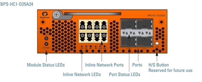
BPS-HC1-D25A24 SX/SR Bypass Combo Module
Bypass Combo Module with two SX/SR (50/125μm multi-mode) inline network port pairs and four regular SFP+ port cages (BPS-HC1-D25A24) (1 Bypass Combo Module BPS-HC1-D25A24)
Before installing the BPS-HC1-D25A24 Bypass Combo Module, the GigaVUE‑HC1 must be running software version 5.0 or higher.
For internal transceiver and loss summary specifications, refer to Bypass Combo Module Specifications.
|
1
|
Bypass Combo Module BPS-HC1-D25A24 |
Features of the 1Gb/10Gb Bypass Combo Module
The 1Gb/10Gb bypass combo module has the following features:
|
■
|
Two Inline network port pairs pass traffic bi-directionally. |
|
■
|
Port pairs that offer optical protection switches for physical bypass. |
|
■
|
Four regular SFP/SFP+ ports that can operate at 1Gb/10Gb, and SFP+ ports that can operate at 10Gb. These ports can be configured as any port type. |
|
■
|
Option to select between bypass or inline modes. |
|
■
|
The hot-swap button is not supported, but the command "card slot <slot id> down" can be used to hot-swap the module from the chassis. |
Inline Network Ports
Connect inline networks to the inline network ports. The inline network ports have built-in protection for power down.
The inline network status LEDs have the following labels:
|
■
|
A1—Inline network LED A (for network 1 through network 2) |
|
■
|
B1—Inline network LED B (for network 1 through network 2) |
|
■
|
M1—Mode LED (on is inline and off is bypass) |
|
■
|
A2—Inline network LED A (for network 1 through network 2) |
|
■
|
B2—Inline network LED B (for network 1 through network 2) |
|
■
|
M2—Mode LED (on is inline and off is bypass) |
Note: In the CLI, the inline network ports are referred to as x5 to x8.
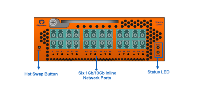
BPS-HC1-D25A60 SX/SR Bypass Combo Module
The BPS-HC1-D25A60 is a multi-mode SR 1Gb/10Gb bypass module. Bypass Modules offer six inline network port pairs each.
Before installing the BPS-HC1-D25A60 Bypass Combo Module, the GigaVUE‑HC1 must be running software version 6.8 or higher.
For internal transceiver and loss summary specifications, refer to Bypass Combo Module Specifications.
|
2
|
Bypass Combo Module BPS-HC1-D25A60 |
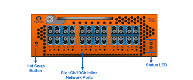
BPS-HC1-D35C60 LX/LR Bypass Combo Module
The BPS-HC1-D35C60 is a single-mode LR 1Gb/10Gb bypass module. Bypass Modules offer six inline network port pairs each.
Before installing the BPS-HC1-D35C60 Bypass Combo Module, the GigaVUE‑HC1 must be running software version 6.7 or higher.
For internal transceiver and loss summary specifications, refer to Bypass Combo Module Specifications.
|
3
|
Bypass Combo Module BPS-HC1-D25C60 |
Features of the 1Gb/10Gb Bypass Combo Module
The 1Gb/10Gb bypass combo module has the following features:
|
■
|
Inline network port pairs pass traffic bi-directionally. |
|
■
|
Port pairs that offer optical protection switches for physical bypass. |
|
■
|
The inline network ports can operate on both 1Gb/10Gb. |
|
■
|
Option to select between bypass or inline modes. |
|
■
|
The hot-swap button is not supported, but the command "card slot <slot id> down" can be used to hot-swap the module from the chassis. |
Inline Network Ports
Connect inline networks to the inline network ports. The inline network ports have built-in protection for power down.
The inline network status LEDs have the following labels:
|
■
|
A1—Inline network LED A (for network 1 through network 2) |
|
■
|
B1—Inline network LED B (for network 2 through network 1) |
|
■
|
M1—Mode LED (on is inline and off is bypass) |
|
■
|
A12—Inline network LED A (for network 1 through network 2) |
|
■
|
B12—Inline network LED B (for network 2 through network 1) |
|
■
|
M12—Mode LED (on is inline and off is bypass) |
Bypass Combo Modules
Security tools such as firewalls and intrusion detection/protection systems are often connected inline on production networks, with traffic flowing from the network segment through the tool and then back onto the production network.
The GigaVUE‑HC1 offers physical and logical Inline Bypass. Physical bypass provides automatic failover protection in the case of a power failure. The bypass combo modules provide the physical bypass function. As it applies to a single pair of inline network ports, the physical bypass function is as follows:
|
■
|
When the module is not powered (either the entire node is powered down or the module is removed from the node), the inline network port pair is in the physical bypass mode. That means that traffic is exchanged directly between network Port A and network Port B of the inline network pair. |
|
■
|
When the module is powered, the mode (inline or bypass) of the inline network port pair is controlled through software. In the physical bypass mode, the inline network port pair behaves exactly as if the module was not powered. In inline mode, the inline network port pair behaves like any other inline network port pair configured to work with an inline tool. |
Modules are hot-swappable. Refer to Hot Swapping Modules for instructions.
Module Status LEDs
The following module status LEDs are located on the front of the bypass combo module:
|
■
|
RDY is the Ready LED. It has the following states: |
|
o
|
RED indicates system booting or module down |
|
o
|
GREEN indicates normal condition |
|
■
|
POWER is the Power LED. It has the following state: |
|
o
|
GREEN indicates the module is receiving power |
Port Status LED
The SFP+ Port Status LED has the following states:
|
■
|
Off indicates that the port is disabled or the link is down |
|
■
|
GREEN indicates that the link is established |


