How to Create a Cluster
Setting up a cluster consists of a number of steps. Refer to the “Creating Clusters: A Roadmap” section in the GigaVUE Fabric Management Guide for detailed information. For configuration examples, refer to the following sections:
Create and Execute the Configuration Plans
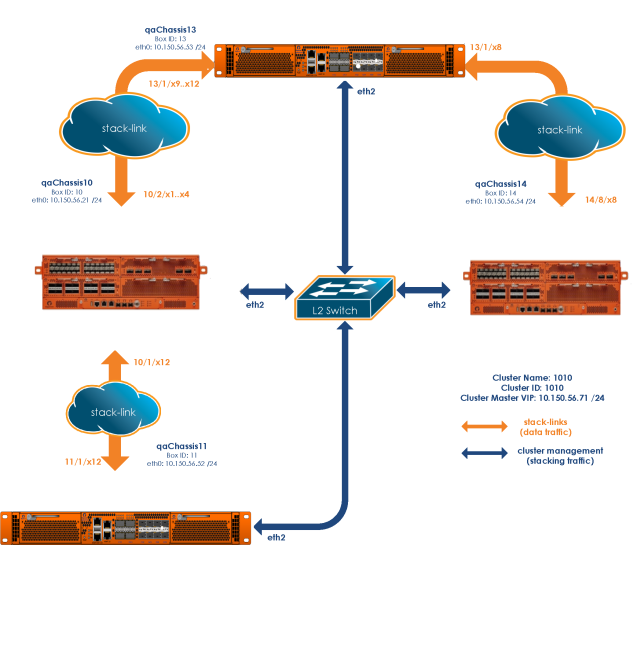
Once you have drawn your cluster topology, it is easy to write up configuration plans for each node in the cluster showing the values for the configuration commands you will need to issue. For example, the plans for the cluster topology in Figure 12-4 could look like those in the following tables.
These plans all use HCCv2 control cards and establish cluster connectivity over the cluster management ports and then go on to set up the stack-links. You cannot establish stack-links between nodes until the cluster itself is communicating.
Note that the easiest way to establish a node’s cluster settings is with the config jump-start script described in the Hardware Installation Guides. The script is illustrated as follows. The values entered for Steps 16-21 matching those in the configuration plan for our first node:
|
Gigamon GigaVUE HC Series Chassis gigamon-0d04f1 login: admin Gigamon GigaVUE HC Series Chassis GigaVUE‑OS configuration wizard Do you want to use the wizard for initial configuration? yes Step 1: Hostname? [gigamon-0d04f1] Node_A Step 2: Management interface? [eth0] Step 3: Use DHCP on eth0 interface? no Step 4: Use zeroconf on eth0 interface? [no] Step 5: Primary IPv4 address and masklen? [0.0.0.0/0] 10.150.52.2/24 Step 6: Default gateway? 10.150.52.1 Step 7: Primary DNS server? 192.168.2.20 Step 8: Domain name? gigamon.com Step 9: Enable IPv6? [yes] Step 10: Enable IPv6 autoconfig (SLAAC) on eth0 interface? [no] Step 11: Enable DHCPv6 on eth0 interface? [no] Step 12: Enable secure cryptography? [no] Step 13: Enable secure passwords? [no] Step 14: Minimum password length? [8] Step 15: Admin password?
Please enter a password. Password is a must.
Step 15: Admin password? Step 15: Confirm admin password? Step 16: Cluster enable? [no] yes Step 17: Cluster interface? [eth0] Step 18: Cluster id (Back-end may take time to proceed)? [default-cluster] 1010 Step 19: Cluster name? [default-cluster] 1010 Step 20: Cluster Leader Preference (Enter higher leader preference for the node to be elected as leader)? [65] Step 21: Cluster mgmt IP address and masklen? [0.0.0.0/0] 10.150.56.71/24
|
How to Use Jump-Start Configuration on GigaVUE®TA Series Nodes
If a license to enable the cluster is not available when first configuring jump-start, you will see the following output:
TA1 (config) # configuration jump-start
GigaVUE‑OS configuration wizard
Step 1: Hostname? [TA1]
Step 2: Management Interface <eth0> ? [eth0]
Step 3: Use DHCP on eth0 interface? [yes]
Step 4: Enable IPv6? [yes]
Step 5: Enable IPv6 autoconfig (SLAAC) on eth0 interface? [no]
Step 6: Enable DHCPv6 on eth0 interface? [no]
Step 7: Enable secure cryptography? [no]
Step 8: Enable secure passwords? [no]
Step 9: Minimum password length? [8]
Step 10: Admin password?
Please enter a password. Password is a must.
Step 10: Admin password?
Step 10: Confirm admin password?
No valid advanced features license found!
You have entered the following information:
1. Hostname: TA1
2. Management Interface <eth0> : eth0
3. Use DHCP on eth0 interface: yes
4. Enable IPv6: yes
5. Enable IPv6 autoconfig (SLAAC) on eth0 interface: no
6. Enable DHCPv6 on eth0 interface: no
7. Enable secure cryptography: no
8. Enable secure passwords: no
9. Minimum password length: 8
10. Admin password: ********
To change an answer, enter the step number to return to.
Otherwise hit <enter> to save changes and exit.
Choice:
Configuration changes saved
Once the license is installed, you can run jump-start again and the steps relating to enabling the cluster will become available, as follows:
Step 11: Cluster enable? [yes]
Step 12: Cluster Interface <eth0> ? [eth0]
Step 13: Cluster id (Back-end may take time to proceed)? [89]
Step 14: Cluster name? [Cluster-89]
Step 15: Cluster mgmt IP address and masklen? [10.115.25.89/21]
Configure Cluster Connectivity – Configuration Plans
|
Configuration Plan for qaChassis 13 (Box ID 13) |
Commands |
|
|
Cluster ID |
1010 |
cluster id 1010 |
|
Cluster Name |
1010 |
cluster name 1010 |
|
Cluster Leader VIP |
10.150.56.71 /24 |
cluster leader address vip 10.150.56.71 /24 |
|
Cluster Control Interface |
eth0 |
cluster interface eth0 |
|
Cluster Mgmt Port IP (eth0) |
zeroconf |
interface eth0 zeroconf(IP Configuration for eth0 obtained automatically through default zeroconf setting) |
|
Enable Clustering |
Yes |
cluster enable |
|
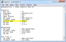
Record Serial Number |
00011 |
show chassis output:
|
|
Box ID |
13 |
chassis box-id 13 serial-num 00011 |
|
Because this is the first node we are configuring with this cluster ID and leader VIP, it automatically assumes the leader role. Configure cluster connectivity for the other nodes before assigning their box IDs to their serial numbers and configuring stack-links from the leader VIP address. |
||
|
Configuration Plan for qaChassis 14 (Box ID 14) |
Commands |
|
|
Cluster ID |
1010 |
cluster id 1010 |
|
Cluster Name |
1010 |
cluster name 1010 |
|
Cluster Leader VIP |
10.150.56.71 /24 |
cluster leader address vip 10.150.56.71 /24 |
|
Cluster Control Interface |
eth0 |
cluster interface eth0 |
|
Cluster Mgmt Port IP (eth0) |
zeroconf |
interface eth0 zeroconf(IP Configuration for eth0 obtained automatically through default zeroconf setting) |
|
Enable Clustering |
Yes |
cluster enable |
|
Record Chassis Serial Number You will need the chassis serial number when you add this node’s box ID to the leader’s database later on. |
80052 |
show chassis |
|
Box ID |
14 |
on page 618). |
|
Configuration Plan for qaChassis 10 (Box ID 10) |
Commands |
|
|
Cluster ID |
1010 |
cluster id 1010 |
|
Cluster Name |
1010 |
cluster name 1010 |
|
Cluster Leader VIP |
10.150.56.71 /24 |
cluster leader address vip 10.150.56.71 /24 |
|
Cluster Control Interface |
eth0 |
cluster interface eth0 |
|
Cluster Mgmt Port IP (eth0) |
zeroconf |
interface eth0 zeroconf (IP Configuration for eth0 obtained automatically through default zeroconf setting) |
|
Enable Clustering |
Yes |
cluster enable |
|
Record Chassis Serial Number You will need the chassis serial number when you add this node’s box ID to the leader’s database later on. |
80054 |
show chassis |
|
Box ID |
10 |
(assigned to normal node from leader using “chassis box-id <box ID> serial-num <serial number>” after cluster connectivity is established. Refer to Connect to the Leader and Add the Member Nodes to the Database |
|
Configuration Plan for qaChassis 11 (Box ID 11) |
Commands |
|
|
Cluster ID |
1010 |
cluster id 1010 |
|
Cluster Name |
1010 |
cluster name 1010 |
|
Cluster Leader VIP |
10.150.56.71 /24 |
cluster leader address vip 10.150.56.71 /24 |
|
Cluster Control Interface |
eth0 |
cluster interface eth0 |
|
Cluster Mgmt Port IP (eth0) |
zeroconf |
interface eth0 zeroconf(IP Configuration for eth0 obtained automatically through default zeroconf setting) |
|
Enable Clustering |
Yes |
cluster enable |
|
Record Chassis Serial Number You will need the chassis serial number when you add this node’s box ID to the leader’s database later on. |
00007 |
show chassis |
|
Box ID |
11 |
(assigned to normal node from leader using “chassis box-id <box ID> serial-num <serial number>” after cluster connectivity is established. Refer to Connect to the Leader and Add the Member Nodes to the Database. |
Connect to the Leader and Add the Member Nodes to the Database
Once you have made the configuration settings necessary to establish cluster connectivity, you need to register each normal node with the leader so that their box IDs and card configuration are in its database. You do this with the chassis box-id <box ID> serial-num <serial number> and card all box-id <box ID> commands in the leader VIP CLI.
Use the following procedure:
| 1. | Log in to the leader VIP CLI. This example uses 10.150.56.71 for the leader VIP address. |
| 2. | For each normal node in the cluster, we need to add the box ID and card configuration. Use the following commands: |
|
Box ID |
Description |
Commands |
|
14 |
Registers the chassis with the serial number of 80052 as box ID 14 and adds all its cards to the database. |
chassis box-id 14 serial-num 80052 card all box-id 14 |
|
10 |
Registers the chassis with the serial number of 80054 as box ID 10 and adds all its cards to the database. |
chassis box-id 10 serial-num 80054 card all box-id 10 |
|
11 |
Registers the chassis with the serial number of 00007 as box ID 11 and adds all its cards to the database. |
chassis box-id 11 serial-num 00007 card all box-id 11 |
|
Note: The box IDs you specify here do not need to match the ones you set up with config jump-start. The leader applies the box ID to the specified chassis serial number with the commands here. However, for the sake of consistency and ease of configuration, it is generally easiest to use matching box IDs. |
||
It can take a minute or two for the card all box-id command to complete. Once it does for all nodes in the cluster, the show cluster global command displays the box IDs you configured in the table. Refer to the next section for an example.
Verify Cluster Connectivity
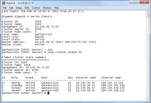
Once you have made the configuration settings necessary to establish cluster connectivity, verify that the connections you expect are there by connecting to the leader VIP address and using the show cluster global brief command. For example:

From here, we can see that all four nodes are connected to the cluster. Each node has an External and an Internal Address as follows:
| External Address – The IP address assigned to the Mgmt port on the control card for each node. When working with a cluster configuration, this IP address is active for CLI and GUI management of the local node. However, cluster-wide tasks should be performed using the virtual IP address for the cluster. This virtual IP address is assigned to whichever node is currently performing the leader role. Should the leader go down, causing the standby node to be promoted to leader, the new leader will take over the virtual IP address for the cluster. |
Note: Active connections to the leader VIP will be dropped when a new node is promoted to the leader role and takes ownership of the address. You can reconnect to the leader VIP to resume operations.
| Internal Address – The IP address assigned to the cluster management port on the control card for this node. This address is used for cluster management traffic. It is referred to as internal because you never work over this interface directly – the cluster uses it for stack management. |
Configure Stack-Links from Leader
Once you have verified that the cluster is successfully communicating, you can connect to the leader VIP, enable the ports for the stack-links, and finally configure the stack-links. Use the port <port-list> params admin enable command to enable ports. Then, per our cluster topology, configure the following stack-links:
|
Stack Links for Cluster 1010 |
Ports |
Commands |
|
qaChassis13 to qaChassis14 |
13/1/x8 to 14/8/x8 |
First, set the port-type to stack for both ends of the stack-link. Then, connect them with the stack-link command: port 13/1/x8 type stack port 14/8/x8 type stack stack-link alias c13-to-c14 between ports 13/1/x8 and 14/8/x8 |
|
qaChassis13 to qaChassis10 |
13/1/x9..x12 to 10/2/x1..x4 |
First, configure the GigaStream on both sides of the stack-link. Then, connect them with the stack-link command: port 13/1/x9..x12 type stack gigastream alias 13stack port-list 13/1/x9..x12 port 10/2/x1..x4 type stack gigastream alias 10stack port-list 10/2/x1..x4 stack-link alias c13-to-c10 between gigastreams 13stack and 10stack |
|
qaChassis10 to qaChassis11 |
10/1/x12 to 11/1/x12 |
stack-link alias c10-to-c11 between ports 10/1/x12 and 11/1/x12 |
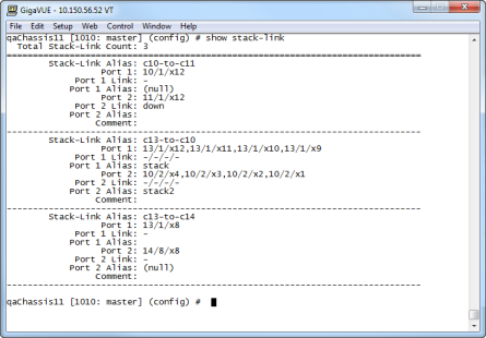
Once you have configured your stack-links, check them with the show-stack-link command to make sure they are up. Figure 4-25 provides an example of the show stack-link output for our sample cluster.

| 1 | Output of show stack-link for Sample Cluster |
The cluster is now up and running. You can log into the leader VIP and configure cross-node packet distribution using standard box ID/slot ID/port ID nomenclature. The following figure illustrates the cluster, along with its configuration.

Join a Node to a Cluster (Out-of-Band)
The simplest way to join a node to a cluster is to modify the cluster ID. Refer to Step 3 in the following procedure. However, a good practice for joining a node to a cluster is to include the following commands:
1(config) # no cluster enable
2(config) # no traffic all
3(config) # cluster id <cluster ID>
4(config) # cluster name <name>
5(config) # cluster leader address vip <IP address> <netmask | mask length>
6(config) # cluster interface <eth>
7(config) # cluster enable
Note: In Step 5, the syntax includes a space between the IP address and the netmask.
Add a Node to an Existing Cluster – Reset to Factory Defaults
Gigamon recommends resetting a GigaVUE‑OS node to its factory settings before adding it to an existing cluster.
If moving a node from one cluster to another, you should use the "reset factory all" command to remove any cluster data in the configs.
To reset factory default settings:
| 1. | Save and upload all configuration files for the node that you want to keep to external storage, including the running configuration. Back up the running configuration using either of the following methods: |
|
Back Up by Copying and Pasting |
(config) # show running-config This command displays the commands necessary to recreate the node’s running configuration on the terminal display. You can copy and paste the output from this command into a text file and save it on your client system. The file can later be pasted back into the CLI to restore the configuration. |
|---|---|
|
Back up to SCP/TFTP/HTTP Server |
(config) # configuration text generate active running upload <upload URL> <filename> This command uses FTP, TFTP, or SCP to upload the running configuration to a text file on remote storage. The format for the <upload URL> is as follows: [protocol]://username[:password]@hostname/path/filename For example, the following command uploads a text configuration file based on the active running configuration and uploads it to an FTP server at 192.168.1.49 with the name config.txt: (config) # configuration text generate active running uploadftp://myuser:mypass@192.168.1.49/ftp/config.txt |
| 2. | Run the following command to reset the node to its factory defaults: |
(config) # reset factory only-traffic
The node reloads automatically.
| 3. | Connect the ports to be used for cluster management traffic. |
| 4. | Run the jump-start script with the following command if it does not appear automatically: |
(config) # config jump-start
| 5. | Follow the jump-start script’s prompts to configure the node, including the cluster settings for the cluster you want to join. |
The reason for this is that both the standalone node and the target cluster have their own name-spaces for traffic-related aliases - maps, tool-mirrors, and so on. When a new node joins a cluster, the system attempts to merge the aliases. However, if there are any duplicate aliases between the standalone node and the existing cluster, there can be destabilizing results for the newly added node, up to and including system exceptions. Because of this, Gigamon recommends resetting a node's settings with the reset factory only-traffic command before adding it to an existing cluster.
Remove a Node from a Cluster and Using as a Standalone
To remove a GigaVUE‑OS node from an existing cluster and apply a saved standalone configuration file, perform the following steps:
| 1. | Remove the node from the cluster by executing the following commands: |
(config) # no chassis box-id <node_boxid_to_be_removed>
(config) #cluster remove <node-id_to_be_removed>
| 2. | Disable the cluster configuration from the node removed in step 1. Use the no cluster enable command. |
| 3. | Run the following command to reset the node to its factory defaults: |
(config) # reset factory only-traffic
The node reloads automatically.
| 4. | Apply the saved standalone configuration file. |


