Supported Topologies
Fabric map support is available for the following topologies:
Refer to the following rules and notes:
- Source port of a fabric map can be either a network port, hybrid port or a vport.
- Destination port of a fabric map can be a tool port, hybrid port, GigaStream, Fabric Port Group or a vport.
- For topologies with leaf and spine clusters:
- Do not configure the spine nodes as source or destination nodes. Source and destination must be configured either in the leaf nodes or in the node/clusters that are connected to the leaf nodes.
- Do not connect standalone nodes or clusters to the spine nodes.
- You can connect the spine nodes to its leaf node. Spine nodes can also be connected to spine nodes of another leaf-spine cluster.
- Do not configure fabric maps in topologies that are not supported. Though GigaVUE-FM allows such configurations, it might lead to unpredictable results.
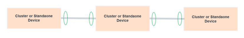
Multihop Topology
In this topology, multiple standalone nodes and/or non-leaf and spine clusters are connected using circuit GigaStreams.
Refer to the following notes:
- Source and destination nodes can be configured anywhere in the topology.
- Redundant links must not be configured between the nodes, that is, there should not be more than one path from source to destination.
The Standalone nodes or clusters can be configured as follows:
The standalone nodes or clusters can also be configured like a tree topology. Refer to the following figure.
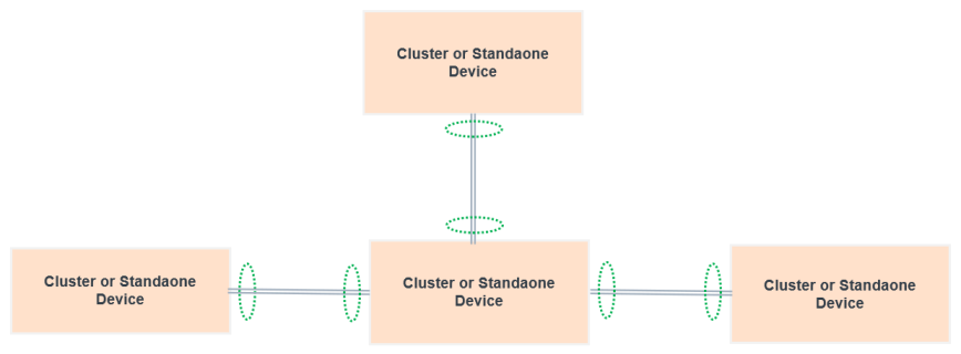
Supported Multihop Topology
The following multihop topology has only one path from source to destination.
Unsupported Multihop Topology
The following multihop topology has more than one path from source to destination and therefore it is not supported.
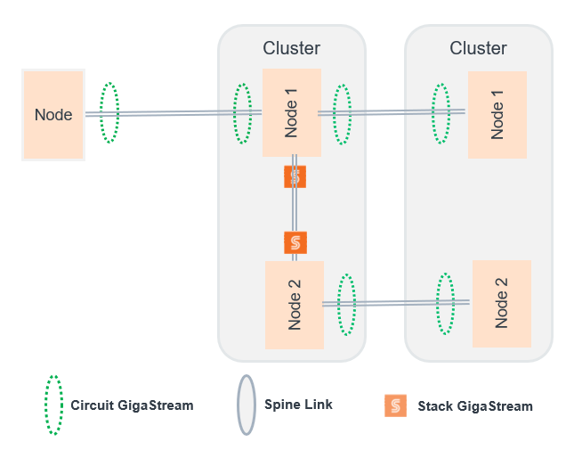
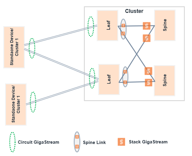
Leaf and Spine Topology
In this topology, a standalone node or a cluster is connected to any one of the leaf nodes in a leaf-spine cluster. It can also be load balanced to multiple leaf nodes of a leaf spine cluster. Refer to the Multi-Path Leaf and Spine section for details.
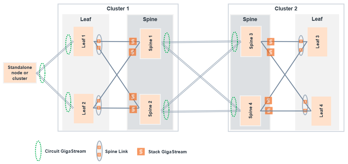
Dual Multipath Leaf and Spine Topology
In this topology, a leaf-spine cluster is connected to another leaf-spine cluster by configuring circuit GigaStreams across the spine nodes. Each spine node in a cluster is load-balanced with spine nodes in another cluster.
Supported Failovers
In a dual multipath leaf and spine cluster topology, traffic from one cluster to another cluster will be routed in case of the following failover scenarios:
- Scenario 1: At least one of the spine nodes in both clusters is in active state.
- Scenario 2: At least one circuit link connecting the spines across the cluster is active.
Scenario 1
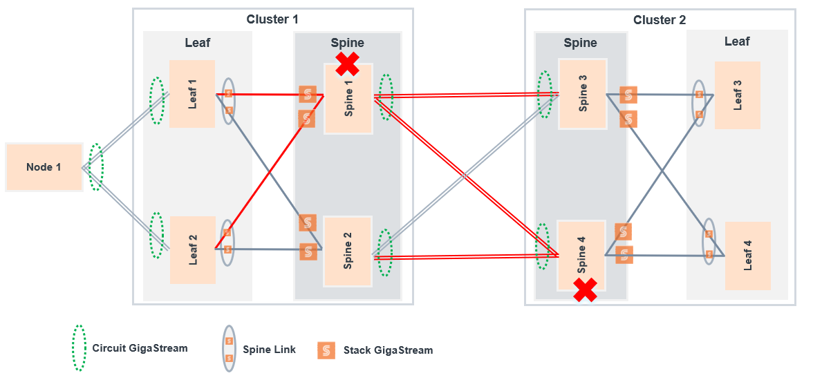
In the above topology:
- Spine nodes 1 and 4 are down.
- Spine nodes 2 and 3 are up.
- Traffic is routed from leaf nodes on cluster 1 to leaf nodes on cluster 2 even though spine 1 and spine 4 are down.
- Traffic flows through the green links between spine 2 and spine 3.
Scenario 2
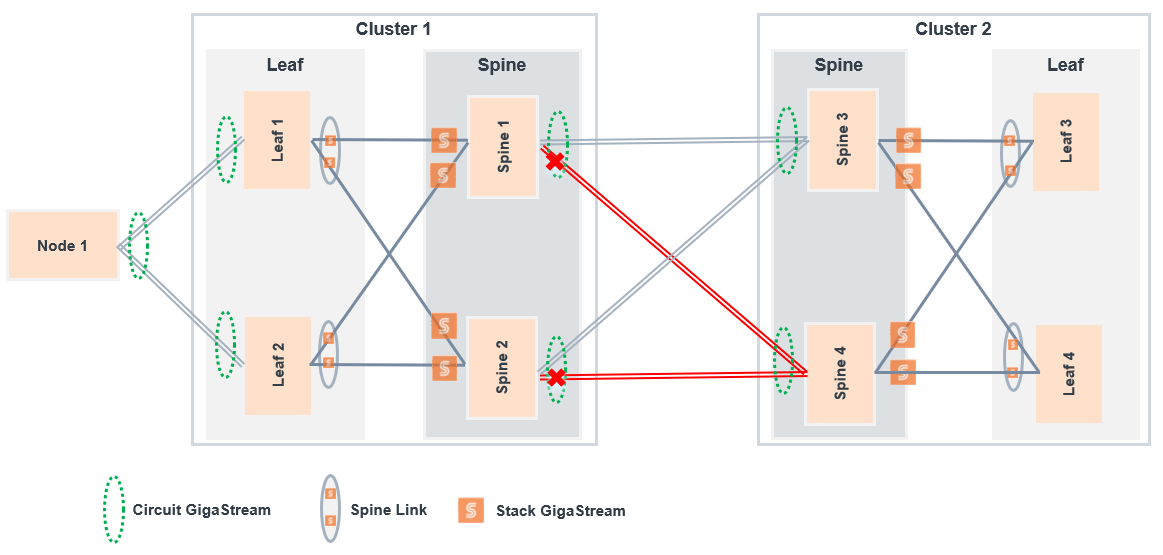
In the above topology:
- All spine nodes are active.
- Circuit GigaStream from Spine 1 to Spine 4 is down.
- Circuit GigaStream from Spine 2 to Spine 4 is down.
- Circuit GigaStream from Spine 1 to Spine 3 is up.
- Circuit GigaStream from Spine 2 to Spine 3 is up.
- Traffic from leaf nodes in cluster 1 are routed to leaf nodes in cluster 2 through circuit links from spine 1 and spine 2 to spine 3.
Thus, even if one of the links is up, traffic is routed across the leaf nodes in the clusters.
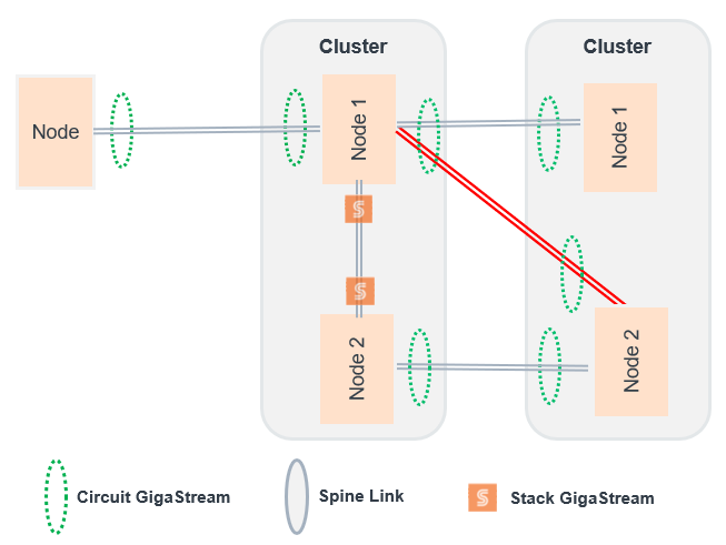
UnSupported Failovers
In a dual multipath leaf and spine cluster topology, traffic from one cluster to another cluster will not be routed in case of the following failover scenarios:
- Scenario 1: Circuit links connecting the spine nodes across cluster is down
- Scenario 2: Spine links connecting the leaf nodes to spine node is down.
Scenario 1
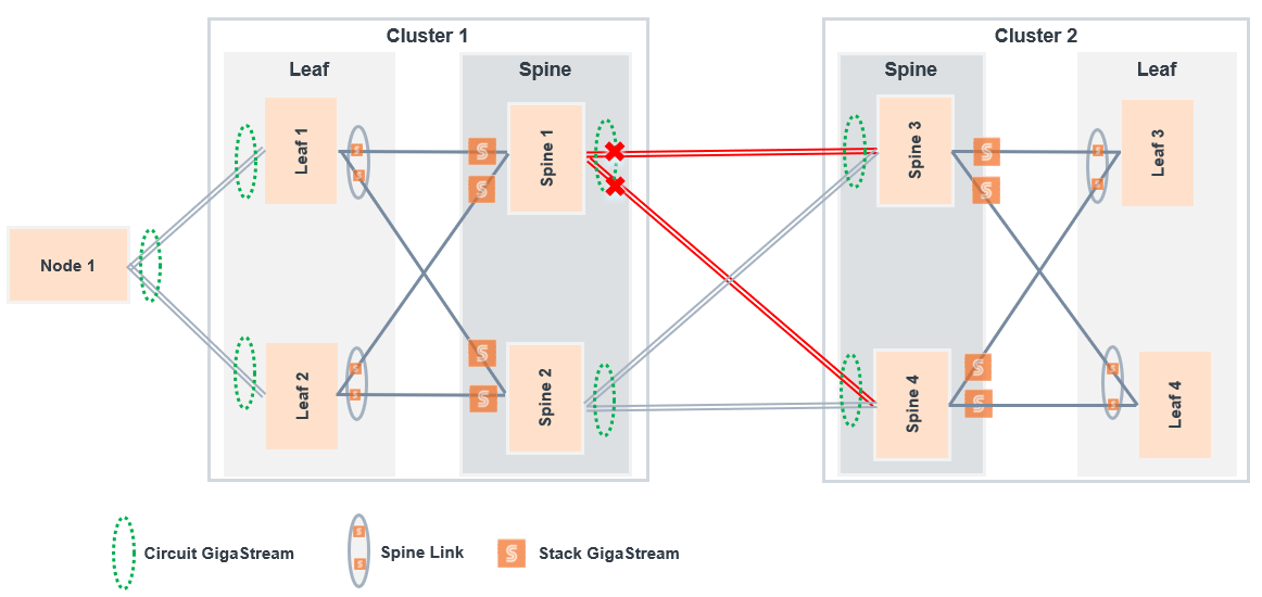
In the above topology:
- Traffic from Leaf 1 and Leaf 2 is load-balanced to spine node 1.
-
Traffic received on Spine 1 will not be delivered to the adjacent cluster as the following circuit GigaStreams are down:
- Circuit GigaStream from Spine 1 to Spine 3
- Circuit GigaStream from Spine 1 to Spine 4.
Scenario 2
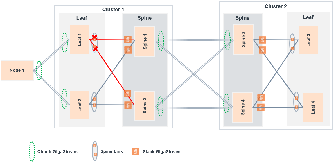
In the above topology, traffic received on leaf 1 will be discarded as the following spine links are down:
- Spine link connecting leaf 1 to spine 1
- Spine link connecting leaf 1 to spine 2


