Introducing the GigaVUE‑HC3 Chassis
The fully-assembled GigaVUE‑HC3 chassis consists of a 3RU, rack-mountable, 19in-wide chassis with management, network, and tool ports at the front and power connections, fans, and access to the control card at the rear. GigaSMART is available with SMT-HC3-C05 installed in the chassis. 1Introducing the GigaVUE‑HC3 Chassis summarizes the bays on the front including modules and extension board, and Rear View of the GigaVUE‑HC3 Chassis summarizes the rear of the GigaVUE‑HC3 chassis including fans and power supply modules.
Note: Refer to Unpacking the GigaVUE‑HC3 Shipment for assembly instructions.
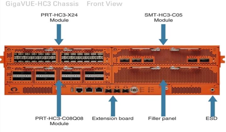
| 1 | Front View of the GigaVUE‑HC3 Chassis |
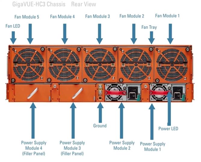
| 2 | Rear View of the GigaVUE‑HC3 Chassis |
Front Components on the GigaVUE‑HC3 Chassis | |
Module Bays | There are four module bays. They are numbered from 1 to 4, starting with top left, then bottom left; top right, then bottom right. (Refer to .) The numbering of the module bays also determines the priority of the modules for power management. For information about power management, refer to Power Management. |
Modules | shows three different GigaVUE‑HC3 modules. Refer to GigaVUE‑HC3 Modules for descriptions of the modules. |
Cable Management | The GigaVUE‑HC3 provides optional cable management. Use it to securely route cables from ports to the left and right side of the node. Refer to Installing Cable Management Left and Right for more information. |
Extension Board | There is an extension board installed at the front of the node. The extension board provides a USB port, console port, a management port, a PTP port, two stack ports, a P/S port and a PPS (IN) port, as well as status LEDs. Refer to GigaVUE‑HC3 Extension Board for more information. |
Rear Components on the GigaVUE‑HC3 Chassis | |
Power Supply Modules | The GigaVUE‑HC3 has load sharing power supply modules (PSMs). The node ships with two PSMs, but can be upgraded to four, thus offering 1+1 or 2+2 power redundancy. Both AC and DC power supply modules are available. Refer to Power Requirements for information on power characteristics of the GigaVUE‑HC3. |
Fan Tray | The fan tray is installed at the rear of the node provide system cooling. The fan tray contains five fan modules with two fans per module. Each fan module can be removed separately from the fan tray. Refer to Fan Tray Procedures for more information. |
The GigaVUE‑HC3 includes a control card installed inside the node, accessible from the rear of the chassis, behind the fan tray. The control card provides switching and processing resources for the entire chassis. It also controls the Mgmt port and console port on the front of the node for network and local administrative access to the GigaVUE‑OS command-line interface (CLI). The Mgmt port and console port are on the extension board. Starting in software version 5.4, Control Card version 2 (CCv2) is available. Refer to GigaVUE‑HC3 Control Cards for more information. | |


