Transceivers
Gigamon provides a variety of transceivers for use with the 100Gb, 40Gb, 25Gb, or 10Gb ports in GigaVUE node’s ports.
Identifying Transceivers
It is not always easy to tell the difference between various transceivers. Use the following tips to keep track of your transceivers:
| SFP+ transceivers use metal bail and latch assemblies. The color of the metal bail corresponds to the SFP+ type, as summarized in the following table. |
|
Media/Transceiver |
Description |
|---|---|
|
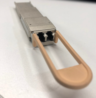
Q28-502 100Gb SR4 QSFP28 |
Beige Pull Tab
|
|
Q28-503 100Gb LR4 QSFP28 |
Blue Pull Tab
|
|
Q28-513 100Gb QSFP28 CWDM4 |
Green Pull Tab
|
|
QSB-512 100Gb QSFP28 BiDi |
Beige Pull Tab
|
|
QSF-502 40Gb SR4 QSFP+ |
Beige Pull Tab
|
|
QSF-503 40Gb LR4 QSFP+ |
Blue Pull Tab
|
|
QSF-506 40Gb QSFP+ Singlemode PLR4 |
Blue Pull Tab
|
|
QSB-501 40Gb SR BiDi QSFP+ RX-only |
Black Pull Tab
|
|
QSB-502 QSFP+ 40Gb BiDi SR Full Duplex (RX/ TX) |
Beige Pull Tab
|
|
SFP-552 25Gb SR SFP28 |
Beige Tab
|
|
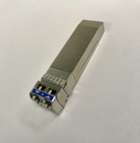
SFP-553 25Gb LR SFP28 |
Blue Tab
|
|
SFP-531 10Gb T SFP+ |
Metal Bail
|
|
SFP-532 10Gb SR SFP+ |
3 Silver Metal Bail
|
|
SFP-533 10Gb LR SFP+ |
Blue Metal Bail
|
|
QSF-507 40Gb QSFP+ ESR |
Beige Pull Tab
|
|
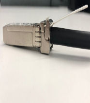
CBL-205 10Gb Direct Attach Copper Cable (DAC) |
White Pull Tab
|
|
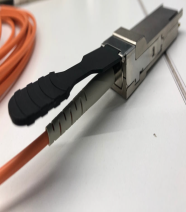
CBL-405, CBL-410, CBL-415 40Gb Active Optic Cable (AOC) |
Black Pull Tab
|


Transceiver Installation Instructions
Gigamon transceivers are keyed and can only be installed in one direction. Transceivers are hot-swappable – they can be installed or removed with the power on or off. Use the following procedures to install and remove transceivers from GigaVUE modules.
Note: Always use an ESD-preventive wrist or ankle strap and ensure that it makes good skin contact when installing or removing transceivers.
The strap can be connected to one of the following:
-
ESD wrist strap connector. The chassis provides a connector at the front of the chassis for this purpose labeled with a ground symbol. The connector is located at the front of the chassis on the lower right.
-
Captive installation screws on an installed module or power supply module.
-
Any unpainted surface on the chassis.
Installing Transceivers
-
Remove the dust cap from the port and set it aside for future use.
-
Orient the transceiver with the opening in the module and insert it into the slot.
-
Push gently but firmly until the transceiver is seated in the slot.
-
Close the latch on the transceiver to lock it into the slot.
Removing Transceivers
-
Disconnect the cable (if any) from the transceiver.
-
If you are removing a fiber-optic transceiver, install dust caps in the transceiver to protect the optical interfaces.
-
Open the latch on the transceiver and gently remove it from the slot.
-
If you are not installing a new transceiver, install a dust cap in the open slot on the module.
For details about the supported transceivers and cable types, refer to GigaVUE-OS Compatibility and Interoperability Matrix.


