BPS-HC3-C25F2G Module
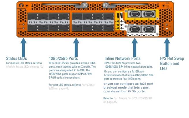
The BPS-HC3-C25F2G module is a bypass combo module with two 100Gb/40Gb SR4 inline network port pairs and sixteen 25Gb/10Gb SFP+ and SFP28 port cages. The inline network ports support physical bypass at speeds of 100Gb or 40Gb. A 4x10Gb and 4x25Gb port breakout mode is supported offering physical bypass at 10Gb/25Gb.
Security tools such as firewall and intrusion detection/protection systems are often connected inline on production networks, with traffic flowing from the network segment through the tool and then back onto the production network.
The GigaVUE‑HC3 offers physical and logical inline bypass. Physical bypass provides automatic failover protection in the case of a power failure. The bypass combo module provide the physical bypass function. As it applies to a single pair of inline network ports, the physical bypass function is as follows:
| When the module is not powered, (either the entire node is powered down or the module is removed from the node), the inline network port pair is in the physical bypass mode. That means that traffic is exchanged directly between network Port A and network Port B of the inline network pair. |
| When the module is powered, the mode (inline or bypass) of the inline network port pair is controlled through software. In the physical bypass mode, the inline network port pair behaves exactly as if the module was not powered. In the inline mode, the inline network port pair behaves as any other inline network port pair configured for working with an inline tool. For information about configuring inline modes, refer to the “inline-network” section of the GigaVUE-OS CLI Reference Guide. |
Before installing the BPS-HC3-C25F2G module, the GigaVUE‑HC3 must be running software version 5.1.01 or higher. Dual speed (100Gb or 40Gb) support is added starting in software version 5.2. The 4x10Gb port breakout mode is added starting in software version 5.3. The 4x25Gb port breakout mode is added starting in software version 5.5.01 in GigaVUE-HC3 CCV2.
Note: The BPS-HC3-C25F2G module does not support 1Gb.
The sixteen 10Gb ports in the BPS-HC3-C25F2G module can be used as network, tool, hybrid, stack, inline-network, or inline-tool ports.
Starting in software version 5.4, SFP28 transceivers support 25Gb.
Note: To support 25Gb functionality, the GigaVUE‑HC3 node must be equipped with Control Card version 2 (CCv2).
For loss summary specifications, refer to Loss Summary Specifications.
For details about the supported transceiver, cable type, fanout, inline ports, and clusters, refer to “GigaVUE-OS Compatibility and Interoperability Matrix”.
Features of 100Gb Bypass Combo Module
The 100Gb bypass combo module has the following features:
| Two inline network port pairs that pass traffic bi-directionally. |
| Port pairs that offer optical protection switch for physical bypass. |
| Sixteen regular 10Gb/25Gb ports that operate with SFP+/SFP28 transceivers. |
| A mode to select either bypass or inline. |
| A module that is hot swappable. Refer to procedures in Removing GigaVUE‑HC3 Modules. |
| 1 | BPS-HC3-C25F2G Module |
BPS-HC3-C25F2G Notes and Rules
Keep in mind the following notes and rules when using the BPS-HC3-C25F2G module:
|
BPS-HC3-C25F2G Notes |
|
Transceivers |
For details about the supported transceiver, cable type, and connectivity specifications, refer to “GigaVUE-OS Compatibility and Interoperability Matrix”. |
Maximum BPS-HC3-C25F2G Modules Per Chassis |
The maximum number of BPS-HC3-C25F2G modules per chassis is four. Each module can support up to two 100Gb/40Gb inline network port pairs, for a total of eight, and sixteen 10Gb ports for a total of sixty-four. |
Network, Tool, Hybrid or Stack Ports |
The sixteen 10Gb/25Gb ports on the BPS-HC3-C25F2G module can be used as a network, tool, hybrid, or stack ports. |
Inline Ports |
The ports on the BPS-HC3-C25F2G module can be configured as inline network or inline tool ports, supporting logical bypass at 10Gb speed. Starting from software version 6.4, Inline ports support logical bypass at 25Gb speed. |
10Gb and 25Gb Ports |
Every group of four ports (quad) can be configured as 25Gb. In one quad, there cannot be a mix of 10Gb and 25Gb ports. By default, all sixteen ports are configured as 10Gb ports. To configure 25Gb, you must configure the port speed as follows: (config) # port x1..x4 params admin enable |
100Gb/40Gb Inline Network Ports |
By default, the inline network ports are 100Gb, but can be configured as either 100Gb or 40Gb, supporting physical bypass at 100Gb or 40Gb port speeds. Each port pair (c1 and c2 or c3 and c4) must be configured with the same port speed. For changing the port speed, refer to the port <port> params speed command in the GigaVUE-OS CLI Reference Guide. |
Inline Network Ports c1..c4
|
The BPS-HC3-C25F2G module includes four 100Gb ports (c1..c4). These ports also support 40Gb speeds. The 40Gb/100Gb ports on the BPS-HC3-C25F2G module can be broken out into 4 times 10Gb ports or 25Gb ports, called subports. The subports will all have the same speed (10Gb or 25Gb). Subports will have x1 to x4 appended to their port ID, for example, 1/1/c2x1. For more information, refer to Port Modes for BPS-HC3-C25F2G. Once a port has been broken out into subports, cable it to an optical patch panel or breakout panel, such as PNL-M341, which takes input from the BPS-HC3-C25F2G module and splits it to four independent output ports. Refer to Breakout Panels. |
Inline Network Ports
Connect inline networks to the inline network ports. The inline network ports have built-in protection for power down.
The inline network ports have the following labels:
| A1—Inline network port A (for network 1) |
| B1—Inline network port B (for network 1) |
| M1—Inline network mode (for network 1) |
| A2—Inline network port A (for network 2) |
| B2—Inline network port B (for network 2) |
| M2—Inline network mode (for network 2) |
The inline network port status LEDs (A1, B1, A2, B2) have the following states:
| OFF indicates that the port link is down |
| GREEN indicates that the link is established |
The physical bypass mode LEDs (M1, M2) have the following states:
| GREEN indicates inline |
| OFF indicates bypass |
In the CLI, the inline network ports are referred to as c1 to c4. Table 2: Port Mapping lists the port mapping.
|
Port |
CLI Port |
|
A1 |
c1 |
|
B1 |
c2 |
|
A2 |
c3 |
|
B2 |
c4 |
For example, if the box ID is 1 and the BPS-HC3-C25F2G module is in slot 3, Table 3: Default Inline Networks lists the default inline networks:
|
Default Inline Network |
Network A Connected To |
Network B Connected To |
|
default_inline_net_1_3_1 |
1/3/c1 |
1/3/c2 |
|
default_inline_net_1_3_2 |
1/3/c3 |
1/3/c4 |
Note: Default inline networks cannot be deleted.
BPS Forwarding LED
Each BPS-HC3-C25F2G inline network port has two LEDs, an upper and a lower, that represent the inline network forwarding state. The upper LED indicates tool flow. The lower LED indicates network flow. Refer to 4 BPS Forwarding LEDs, Upper and Lower.
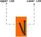
| 4 | BPS Forwarding LEDs, Upper and Lower |
Table 5: Inline Network Forwarding States and LED Descriptions lists the inline network forwarding states and the color of the upper and lower LEDs for each state.
Port Modes for BPS-HC3-C25F2G
The port breakout modes are as follows:
| 4x10G—Specifies the 4x10G port breakout mode. This mode provides a 4 x 10Gb breakout option for 40Gb/100Gb ports. |
| 4x25Gb- Specifies the 4x25G port breakout mode. This mode provides a 4 x 25Gb breakout option for 40Gb/100Gb ports |
| none—Specifies no port breakout mode. This is the default mode for GigaVUE nodes. |
Each of the 40Gb/100Gb inline network protected port pairs (c1 and c2, or c3 and c4) can be broken out into four times 10Gb ports, called subports.
The port speed will be automatically configured to 40Gb/100Gb when the parent port is configured to a port breakout mode of 4x10Gand 4x25Gb. The subports will all have the same speed (10Gb/25Gb). Subports will have x1 to x4 appended to their port ID, for example, when port 1/1/c2 is configured to 4x10G mode, the subports will be: 1/1/c2x1, 1/1/c2x2,
1/1/c2x3, and 1/1/c2x4.
The subports on the BPS-HC3-C25F2G module will only have a port type of inline-network. After configuring the 4x10G and 4x25Gb mode, there will be a maximum of sixteen 10Gb/25Gb ports (eight inline network protected port pairs). Refer to Table 6: Default Inline Networks in 4x10G or 4x25Gb Mode.
For example, if the box ID is 1, the BPS-HC3-C25F2G module is in slot 3, and both port pairs are broken out, Table 6: Default Inline Networks in 4x10G or 4x25Gb Mode lists the default inline networks:
|
Default Inline Network |
Network A Connected To |
Network B Connected To |
|
default_inline_net_1_3_1_1 |
1/3/c1x1 |
1/3/c2x1 |
|
default_inline_net_1_3_1_2 |
1/3/c1x2 |
1/3/c2x2 |
|
default_inline_net_1_3_1_3 |
1/3/c1x3 |
1/3/c2x3 |
|
default_inline_net_1_3_1_4 |
1/3/c1x4 |
1/3/c2x4 |
|
default_inline_net_1_3_2_1 |
1/3/c3x1 |
1/3/c4x1 |
|
default_inline_net_1_3_2_2 |
1/3/c3x2 |
1/3/c4x2 |
|
default_inline_net_1_3_2_3 |
1/3/c3x3 |
1/3/c4x3 |
|
default_inline_net_1_3_2_4 |
1/3/c3x4 |
1/3/c4x4 |
Note: Default inline networks cannot be deleted.
Since there is only a single pair of LEDs for the inline networks on the BPS-HC3-C25F2G module, when a port is broken out, the BPS forwarding LED only represents the first inline network protected port pair. Refer to BPS Forwarding LED.
Note: Each port can only have one mode.
There are rules for configuring parent ports and subports. For more information, refer to the port command in the reference section of the GigaVUE-OS CLI Reference Guide.


