Introducing the GigaVUE‑HC1 Chassis
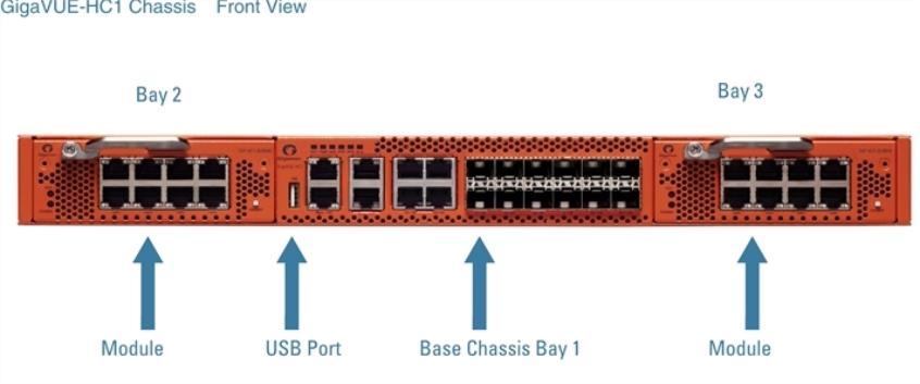
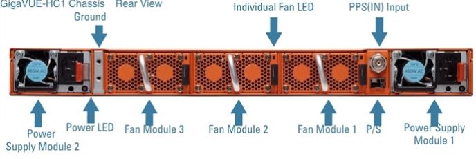
The fully-assembled GigaVUE‑HC1 chassis consists of a 1RU, rack-mountable, 19 in-wide chassis with management, network, and tool ports at the front and power connections and fans at the rear. Front View of the GigaVUE‑HC1 Chassis summarizes the bays and components at the front and Rear View of the GigaVUE‑HC1 Chassis summarizes the rear of the GigaVUE‑HC1 chassis.
The base chassis provides twelve 10Gb/1Gb SFP+ network ports, four 1Gb/100Mb RJ45 copper ports, and GigaSMART, capable of processing packets at 20Gb. The faceplate of the chassis has ports for MGMT interface, cluster management, PTP and PPS over Ethernet, Console, as well as a USB port.
Note: The GigaVUE‑HC1 chassis arrives from the factory with power supply modules and fans installed. The GigaVUE‑HC1 modules are shipped separately. Refer to Unpacking the GigaVUE‑HC1 Shipment for assembly instructions.
| 1 | Front View of the GigaVUE‑HC1 Chassis |
| 2 | Rear View of the GigaVUE‑HC1 Chassis |
|
Front Components on the GigaVUE‑HC1 Chassis |
|
|
Module Bays |
The base chassis is in the center and numbered 1. Slots (bays) are numbered 2-3 from left to right. |
|
Base Chassis |
The GigaVUE‑HC1 includes a base chassis which holds the management and processing components installed inside the unit. It is located in the center of the front of the chassis. Note: The base chassis is not hot-swappable. The base chassis also controls the Mgmt port and console port on the front of the node for network and local administrative access to the GigaVUE‑OS command-line interface (CLI). The base chassis provides twelve 10Gb/1Gb SFP+ network ports, four 1Gb/100Mb RJ45 copper ports, and GigaSMART, capable of processing packets at 20Gb. Refer to GigaVUE‑HC1 Base Chassis for more information. |
|
Rear Components on the GigaVUE‑HC1 Chassis |
|
|
Power Supply Modules |
The GigaVUE‑HC1 includes two separate power supply modules already installed at the rear of the node. Each power supply module can independently operate the GigaVUE‑HC1 for 1+1 system redundancy and are hot swappable. Separate AC and DC power units are available. Refer to Power Requirements for information on power characteristics of the GigaVUE‑HC1. Refer to Module Removal and Replacement Procedure (Hot Removal) for more information on hot-swapping the module. |
|
Fan Trays |
The fan trays installed at the rear of the node provide system cooling. Fan trays are also hot-swappable.Refer to Module Removal and Replacement Procedure (Hot Removal) for more information on hot-swapping the module. |
|
PPS(IN) |
The GigaVUE‑HC1 includes a BNC connector for an optional PTP 1PPS reference clock. (Reserved for future use). |
|
P/S |
Inter-chassis primary and secondary connection (Reserved for future use). |


