5G Cloud Nokia IMS Solution (Non-SBI)
Nokia HEP3 (Homer Encapsulation Protocol Version 3) is a binary encapsulation format that Nokia uses for control-plane traffic in the IMS core and across 3G and 4G network functions. HEP3 efficiently encodes protocol metadata and payloads so that Nokia core network solutions can handle diverse packet types.
In this solution, the 5G-Cloud application processes non-SBI IMS control traffic that Nokia vTAPs export as HEP3 over TCP, in clear text or protected with mTLS. 5G-Cloud also supports non-SBI HEP3 traffic from 3G and 4G network functions. It terminates the TCP session, decodes the HEP3 payloads, and exposes the non-SBI control traffic for monitoring without performing IP address translation.
How Nokia HEP3 IMS Solution works
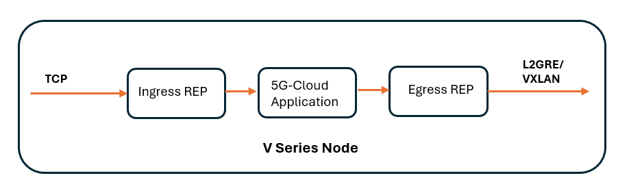
The following image shows the ingress and egress data flow through the V Series Node for Nokia HEP3 IMS solution.
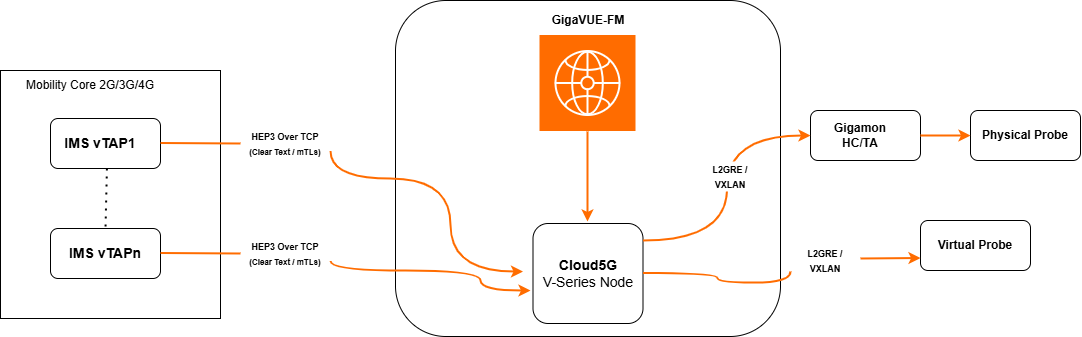
Traffic from client vTAP systems (in clear text or secured with mTLS) travels over TCP to the V Series node. The 5G-Cloud application receives this TCP traffic, terminates the TCP connections, decodes the HEP3 payloads, and synthesizes the data for monitoring.
GigaVUE‑FM serves as the centralized management platform that orchestrates the visibility fabric, including the 5G-Cloud V Series nodes. The V Series nodes inspect, aggregate, and process the incoming traffic. After processing, the nodes encapsulate the traffic using L2GRE or VXLAN tunneling protocols and forward it to probes as follows:
Physical probe- If IP connectivity is not available, the node sends traffic to a GigaVUE HC or GigaVUE TA Series device, which aggregates and distributes traffic to the probe after decapsulation.
Virtual probe- If IP connectivity is available, the node forwards the processed traffic directly to the virtual probe for detailed inspection and analytics.
This end-to-end solution provides comprehensive visibility into 5G IMS control-plane traffic and supports efficient monitoring and performance analysis across both physical and cloud-based infrastructures.
Configure Nokia IMS HEP3 Solution (Non-SBI)
In GigaVUE-FM, you must do the following to add the 5G‑Cloud IMS integration to either a new or existing monitoring session of a Monitoring Domain:
Pre-requisite:
Before starting, ensure that:
-
You have deployed the V Series nodes and added them to a monitoring domain in GigaVUE-FM.
-
IMS vTAPs can reach the V Series node over TCP on the HEP3 collector IP address and port.
-
You must upload CSV files containing a valid FQDN and a valid IPv4/IPv6 address. Refer to Add CSV file for IP Mapping.
-
Create New or Use Exisiting Monitoring Session
In GigaVUE-FM, go to the monitoring domain that will carry IMS HEP3 traffic. You can add the 5G‑Cloud aplication, to a new or existing monitoring session of a Monitoring Domain.
-
New Monitoring Session - Add the 5G-Cloud application after creating a new Monitoring Session and when the GigaVUE-FM canvas appears. Refer to Create a Monitoring Session section in the respective GigaVUE Cloud Suite Deployment Guide.
-
Existing Monitioring Session - Select any existing Monitoring Session and go to TRAFFIC PROCESSING tab. The GigaVUE-FM canvas appears.
-
- Create an ingress REP to receive the data over TCP
- On the canvas, create an ingress raw endpoint (REP) on the V Series node to receive HEP3/TCP from the IMS vTAPs.
- Configure the listening IP address and TCP port that the vTAPs use as the HEP3 collector.
Refer to Create Raw Endpoint (VMware vCenter), Create Raw Endpoint (OpenStack), or Create Raw Endpoint (Third Party Orchestration) for platform-specific steps.
- Configure Nokia HEP3 in 5G-Cloud Application
To add a 5G-Cloud application:
| 1. | In the canvas, drag and drop the 5G-Cloud application and select Details. The 5G-Cloud quick view appears. |
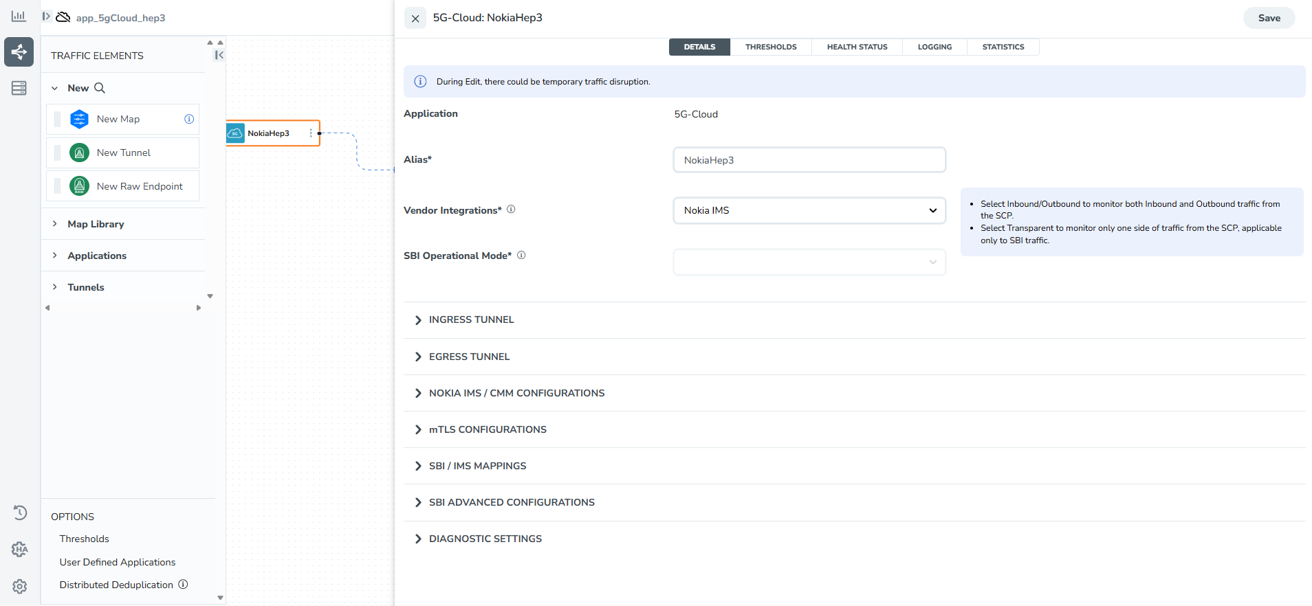
| 2. | On the application quick view, enter or select the required information as described in the Reference - Configuration Table . |
Note: It is recommended to maintain a 60-90 second delay when undeploying and deploying a Monitoring Session in GigaVUE-FM.
Reference - Configuration Table
|
Field |
Description |
||||||||||||||||||
|
Application |
The name 5g-Cloud appears by default. |
||||||||||||||||||
|
Alias |
Enter the required alias name. (for example: NokiaHep3) |
||||||||||||||||||
|
Vendor Integrations |
From the drop-down list, select Nokia IMS. |
||||||||||||||||||
|
SBI Operational Mode |
The Operational Mode is grayed out when you select Nokia CMM or Nokia IMS. |
||||||||||||||||||
|
Ingress Tunnel |
|||||||||||||||||||
|
Type |
Specify the tunnel type. The default is TCP. |
||||||||||||||||||
|
Listening IP |
Specify the tunnel's local listen IP address to receive packets. |
||||||||||||||||||
|
Listening Port |
Specify the tunnel's local listening port to bind for receiving packets. The application listens to the traffic on the specified port. Enter a value between 1 and 65535. |
||||||||||||||||||
|
Source Port |
Specify the tunnel destination port to send packets. Enter a value between 1 and 65535. |
||||||||||||||||||
|
Egress Tunnel |
|||||||||||||||||||
|
Type |
Specify the tunnel type. Available tunnel types are:
|
||||||||||||||||||
|
Tool IP |
Specify the remote IP address to which you want to send the packets. |
||||||||||||||||||
|
Destination Port |
Specify the tunnel destination port to send the packets. Enter a value between 1 and 65535. |
||||||||||||||||||
|
Source IP |
Specify the source IP address to use when sending the packet. |
||||||||||||||||||
|
Source Port |
Specify the tunnel source port to bind when sending packets. Enter a value between 1 and 65535. |
||||||||||||||||||
|
Tool MTU |
Specify the tool port MTU:
|
||||||||||||||||||
|
VNI ID (Applicable only when the selected tunnel type is VXLAN) |
Specify the ID for VXLAN traffic. Enter a value between 0 and 16777215. |
||||||||||||||||||
|
L2GRE Key (Applicable only when the selected tunnel type is L2GRE) |
Specify the key for the L2GRE tunnel type. Enter a value between 0 and 4294967295. |
||||||||||||||||||
|
Nokia IMS / CMM Configuration |
|||||||||||||||||||
|
Number of Ingress TCP Connections |
Specify the number of concurrent TCP connections VTAP can establish. Enter a value between 128 and 2048. The default value is 1024. |
||||||||||||||||||
|
Number of Egress TCP Flows |
Specify the total number of TCP flows allocated for tracking non-SBI traffic.
|
||||||||||||||||||
|
Egress TCP Flow Timeout |
Specify the timeout value for an Egress TCP flow in seconds. Enter a value between 30 and 7200 seconds. The default is 900 seconds. Note: If no packets are received within the configured time, the TCP flow will terminate due to a timeout. |
||||||||||||||||||
|
Number of Receiver Threads |
Specify the number of receiver threads for processing incoming packets. Enter a value between 1 and 128. The default value is 8. |
||||||||||||||||||
|
Number of Egress SCTP Flows |
Specify the total number of SCTP flows allocated to track non-SBI traffic. Enter a value between 128 and 2000000. The default value is 1024. |
||||||||||||||||||
|
Egress SCTP Flow Timeout |
Specifies the timeout value for an Egress SCTP flow in seconds. Enter a value between 30 and 7200. The default value is 900 seconds. Note: If no packets are received within the configured time, the SCTP flow will terminate due to a due to timeout. |
||||||||||||||||||
|
mTLS Configuration |
|||||||||||||||||||
|
mTLS |
Use the toggle button to enable or disable mTLS encryption and decryption in Monitor Mode. |
||||||||||||||||||
|
mTLS key |
|
||||||||||||||||||
|
SBI / IMS Mappings Refer to Add CSV file for IP Mapping section for more details. |
|||||||||||||||||||
|
FQDN Mapping |
Use this option to provide mappings between Fully Qualified Domain Names and IP addresses for all Network Functions in the network.
|
||||||||||||||||||
|
Network Function Instance Mapping (Optional) |
Use this option to provide mappings between NF Instance IDs and IP addresses for all Network Functions in the network.
|
||||||||||||||||||
|
User Agent Mapping (Optional) |
Use this option to provide mappings between User Agents and IP addresses for all Network Functions in the network.
|
||||||||||||||||||
|
Service Mapping |
Use this option to map ephemeral attribute values to standard service attributes and define service-specific actions.
Refer to Reference - Service Map Field Definitions section for example details. |
||||||||||||||||||
|
SBI Advanced Configuration Note: The below configurations apply only to SBI traffic and will not be used for non-SBI traffic. |
|||||||||||||||||||
|
TCP Server Ports |
Specify the TCP server port or port range to enable TCP communication between endpoints.
Note: TCP communication is allowed only on the configured ports. |
||||||||||||||||||
|
Number of TCP Flows |
Specify the total number of TCP Flows allocated for tracking active TCP Flows.
|
||||||||||||||||||
|
Number of Transaction Flows |
Specify the total number of Transaction Stream flows allocated for tracking active Transaction. Refer to Recommend Form Factor for VMware vCenter (Instance Types) for more details. Streams:
|
||||||||||||||||||
|
TCP Flow Timeout |
Specify the TCP flow timeout value.
|
||||||||||||||||||
|
SCP Transaction Timeout |
Specify the Transaction timeout value.
|
||||||||||||||||||
|
Minimum TCP Client Port |
Specify the starting port number for Synthesize Flow.
|
||||||||||||||||||
|
Maximum TCP Client Port |
Specify the end port number for the Synthesize Flow.
|
||||||||||||||||||
|
SCP Processing Threads |
Specify the number of worker threads for processing In-Out packets.
|
||||||||||||||||||
|
TCP Client Ports per Thread |
Specify the number of TCP client ports for each worker thread.
|
||||||||||||||||||
|
Header Index |
Enable or disable the header indexing. The default option is disabled. |
||||||||||||||||||
|
Header Compression Code |
Enable or disable the header compression code. The default option is disable. |
||||||||||||||||||
|
Gigamon Header |
Enable or disable the Gigamon Header. The default option is Enable. |
||||||||||||||||||
|
Diagnostic Settings |
|||||||||||||||||||
|
Log Directory |
Specify the path to store the log files. |
||||||||||||||||||
|
Application Log Level |
Select the severity log level of the events from the following options:
|
||||||||||||||||||
|
Packet Capture Level |
Select the packet capture level from the drop-down list:
|
||||||||||||||||||
|
Packet Capture Timestamp |
Select the required timestamp used to save the Egress PCAPs. The available timestamps are:
Note: Timestamp option is disabled if the Packet capture level is set to None. |
||||||||||||||||||
|
Message Trace Log Level |
Select the 5G-Cloud CSV log level from the drop-down list.
|
||||||||||||||||||
-
Create links between the ingress REP, 5G-Cloud, and egress REP
-
On the canvas, draw a link from the ingress raw endpoint to the 5G-Cloud application.
-
Create an egress raw endpoint (REP) for the target probe or GigaVUE HC/TA device (using the same raw endpoint procedures as in Step 2).
-
Draw a link from the 5G-Cloud application to the egress raw endpoint.
-
Deploy the Monitoring Session
-
After adding all the required elements to the canvas, to deploy the session do the following:
- From the Actions menu, select Deploy.
After successful deployment on all the V Series Nodes, the status appears as Success on the Monitoring Sessions page.
-
View the Deployment Report
-
You can view the Monitoring Session Deployment Report in the SOURCES and V SERIES NODES tab.
-
When you select the Status link, the Deployment Report is displayed.
-
When the deployment is incorrect, the Status column displays one of the following errors:
-
Success: Not deployed on one or more instances due to V Series Node failure.
- Failure: Not deployed on all V Series Nodes or Instances.
-
-
-
Download Logs - 5G-Cloud application
You can view the log files of a V Series Node or download them as .CSV or .txt files.
To download the log files to a local environment:
-
Go to Traffic > VIRTUAL > select your cloud platform.
-
Select the required Monitoring Session and go to TRAFFIC PROCESSING tab. On the cloud5g application, click the
 menu button and select Details. Go to LOGGING in the quick view. The Logging page displays the logs currently available.
 -
Select the required Days, Timestamps, File Name, and Type (TextLog and FlowStats) details.
-
Select the log files to download, and then click Download > Files. The system downloads the selected files to your local environment.
-
Add CSV file for IP Mapping
To add the CSV file for IP mapping:
| 1. | Go to Inventory > VIRTUAL > select your cloud platform, and then click Settings > 5G-Apps. The 5G-Apps Configuration page appears. |
| 2. | Click New. Enter the name for the CSV file in the Alias field. |
| 3. | From the Type drop-down list, select one of the following. You can also choose to download the template using the Download Template option and add the required entries. |
| 5G-Cloud FQDN - Add the CSV file containing a valid FQDN ID and a valid IPv4/IPv6 address for IP mapping. |
Header Details
Example
FQDNID
abc.xyz.com
IngressIP1
1.1.1.1
IngressIP2
2.2.2.2
IngressPort
100
EgressIP
3.3.3.3
NFType
SMF
NFLocation
US
IMSIP
1001:0008:85a2:0000:0000:8f1e:0340:7110
IMSIntfName
100 200
IMSMask
96
IMSType
nef
Notes:
The fields fqdnID and ingressIPAddress1 are mandatory. All other fields are optional.
The fields imsipaddress, imsinterfacename, imsmask and imstype are applicable only when the Integrated solution Vendor is "Nokia HEP3".
| 5G-Cloud NF Instance - Add the CSV file containing a valid NF instance ID and a valid IPv4/IPv6 address for IP mapping. |
Header Details
Example
NFID
amf.local
ingressIPAddress1
1.1.1.1
ingressIPAddress2
2.2.2.2
IngressPort
100
egressIPAddress
3.3.3.3
NFType
AMF
NFLocation
US
Note: The fields NFID and ingressIP1 are mandatory. All other fields are optional.
| 5G-Cloud UA - Add the CSV file containing a valid user agent ID and a valid IPv4/IPv6 address for IP mapping. |
Header Details
Example
useragentid
nef.nb.5gc.mc005.mcc580.yournetwork
ingressIPAddress
1.1.1.1
NFType
AMF
NFLocation
US
Note: The fields useragentID and ingressIPAddress are mandatory. All other fields are optional.
| 5G-Cloud Service Map - Add the CSV file containing valid ephemeral port details and a valid IPv4/IPv6 address for IP mapping. Refer to Reference - Service Map Field Definitions for header details and examples. |
| 4. | Click Choose File in the File Name field to upload the CSV file into GigaVUE-FM. |
| 5. | Click Validate to validate the CSV file. |
| 6. | Click Save to add the CSV file. |
Note:
- When a new mapping table is uploaded, the system validates the relevant fields for duplicate entries.
- If duplicate values are detected, a validation error is displayed.
- For the following tables: 5G-Cloud FQDN, 5G-Cloud NF Instance and 5G-Cloud UA, the mapping file can still be saved with duplicate entries after all other validation errors are resolved by selecting Save Anyway.
Recommended VM Specifications
The configuration of the 5G-Cloud Nokia HEP3 application should be performed on extra-large and large VMs.
| Configuration specifications for Extra Large VM: |
| vCPUs: 26 |
| Memory: 32 GB |
| Disk Space: 80 GB |
Note: Nokia HEP3 configuration on extra‑large VMs is supported only through the Third‑Party Orchestration method.
| Configuration specifications for Large VM: |
| vCPUs: 8 |
| Memory: 16 GB |
| Disk Space: 80 GB |
| Supported Ports: 1 Management interface, 1 ingress, and 1 egress interfaces. |
| It is recommended to use SRIOV enabled drivers for better performance and higher throughput. Refer to Configure GigaVUE Fabric Components using VMware ESXi topic for more details. |
Reference - Service Map Field Definitions
Service mapping normalizes SIP traffic by converting vendor‑specific or ephemeral ports to standard SIP service ports (such as 5060). GigaVUE-FM matches incoming SIP control messages against configurable rules and, when a rule applies, rewrites the source and/or destination port before forwarding the traffic. This ensures that monitoring tools that rely on standard SIP ports continue to work without any changes.
Refer below for field specific details:
Note: All fields except sipMessageType, srcPortMap, and dstPortMap are mandatory.
| 1. | srcIP - Source IP address of the SIP traffic, as carried in HEP3. You can specify a single IPv4 / IPv6 address, a prefix, or ipany to match any address. |
Example:
| ipany – matches SIP traffic from any source IP. |
| 1.1.1.1 – matches only traffic coming from 1.1.1.1. |
| 2. | dstIP - Destination IP address of the SIP traffic. You can specify a single IPv4 / IPv6 address, a prefix, or ipany to match any address. |
Example:
| ipany – any destination IP. |
| 2.2.2.2 – match traffic going to 2.2.2.2. |
| 3. | srcPort - Source port number of the SIP traffic. You can use a specific port to target a known source, or portany to match all source ports. |
Example:
| portany – match SIP traffic regardless of the source port. |
| 5060 – match only when the source port is 5060. |
| 4. | dstPort - Destination port number of the SIP traffic. |
Example:
| portany – any destination port. |
| 5060 – only traffic with destination port 5060. |
| 5. | protocolFamily - Identifies the IP family of the traffic. |
Example:
| IPv4 SIP traffic. |
| IPv6 SIP traffic. |
| 6. | transportProtocol - Identifies the L4 transport protocol (TCP or UDP). |
Note: This field accepts only tcp or udp; it does not support integer values.
| 7. | applicationProtocol - Encodes the application protocol type carried in the HEP3 encapsulation. |
Example:
| 1 – match SIP messages. |
| 8. | interfaceName - Identifies the Nokia interface number on which the traffic is received. |
Example:
| 90 – match traffic received on Nokia HEP3 vTAP interface 90 (IMS Non‑SBI). |
| 9. | Direction - Traffic direction from the node’s point of view. |
Example:
| ingress – apply this rule only to traffic arriving at the node. |
| egress – apply this rule only to traffic sent out from the node. |
| 10. | sipMessageType - Tells whether the SIP message is a request or a response. |
Example:
| request – map ports only for SIP requests. |
| response – map ports only for SIP responses. |
| 11. | action - Specifies what the 5G Cloud application does with matching traffic. |
Example:
| portmap – change source and/or destination ports as specified in srcPortMap / dstPortMap. |
| discard – drop matching traffic. |
| ignore – match but do not modify the ports. |
| 12. | srcPortMap - Applies only to server response frames. Use a valid port number in response frames (sipMessageType = response) and set it to portany for request frames. |
Example:
| 5060 – set the source port to 5060 for matching SIP responses. |
| portany – keep the original source port. |
| 13. | dstPortMap - Applies onto client-to-server request frames. Use a valid port number in request frames (sipMessageType = request) and set it to portany for response frames. |
Example:
| 7777 – set the destination port to 7777 for matching SIP requests. |
| portany – keep the original destination port. |
FHA Dashboards for 5G-Cloud Applications
After configuring the 5G-Cloud application, you can monitor the statistics for Nokia HEP3 by the reports displayed in the Dashboard. To access the details, refer to FHA Dashboards for 5G-Cloud Applications.


