5G Cloud Nokia HEP3 Support (SBI)
Note: CMM Solution is now available as an Early Access feature, giving you the opportunity to explore its capabilities before the general availability (GA).
Nokia 5G network functions use the HEP3 binary format to encode and send packets. HEP3 supports both HTTP2 and TCP protocols, enabling efficient traffic transmission across core network functions. This solution supports traffic processing from Nokia Cloud Mobility Manager (CMM), and the Service Communication Proxy (SCP).
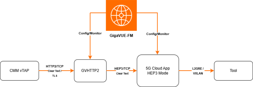
Cloud Mobility Manager (CMM) includes AMF and MME network functions. It generates both Service-Based Interface (SBI) and non-SBI traffic and sends it over HTTP2. The gvHTTP2 application receives CMM traffic and forwards it to the 5G Cloud application, which synthesizes SBI and non-SBI payloads into L2GRE/VXLAN packets before sending them to probes. This approach provides extended visibility across 5G core interfaces and enables operators to monitor both SBI and non-SBI traffic seamlessly.
How Nokia HEP3 Solution works
Nokia vTAP systems in the mobility core send HEP3 data over both HTTP2 and TCP. The system supports traffic from the network functions:
Nokia CMM Solution
Note: CMM Solution is now available as an Early Access feature, giving you the opportunity to explore its capabilities before the general availability (GA).
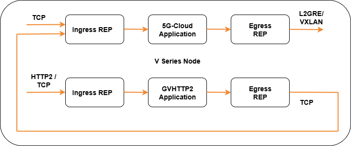
The following image shows the ingress and egress data flow through the V Series Node for Nokia HEP3 solution.
The Cloud Mobility Manager (CMM) function includes key control-plane elements such as AMF and MME. CMM generates both SBI and non-SBI traffic, making it central to mobility management in the 5G Core.
-
CMM vTAPs sends traffic HEP3 over HTTP/2 in stream mode. This traffic is transmitted as HTTP2 over TCP, encrypted either in cleartext or TLS.
-
Further the GVHTTP2 V Series Node transmits all processed traffic to the 5G-Cloud VM using HEP3 over TCP.
-
Next the traffic is tunneled using L2GRE/VXLAN to the probe.
-
The GigaVUE-FM provides configuration and monitoring.
Configure Nokia HEP3 in 5G-Cloud Application
Pre-requisite:
-
You must upload CSV files containing a valid FQDN and a valid IPv4/IPv6 address. Refer to Add CSV file for IP Mapping.
You can add a 5G-Cloud application to:
| New Monitoring Session - Add the 5G-Cloud application after creating a new Monitoring Session and when the GigaVUE-FM canvas appears. Refer to Create a Monitoring Session section in the respective GigaVUE Cloud Suite Deployment Guide. |
| Existing session - Select any existing Monitoring Session and go to TRAFFIC PROCESSING tab. The GigaVUE-FM canvas appears. |
To add a 5G-Cloud application:
| 1. | In the canvas, drag and drop the 5G-Cloud application and select Details. The 5G-Cloud quick view appears. |
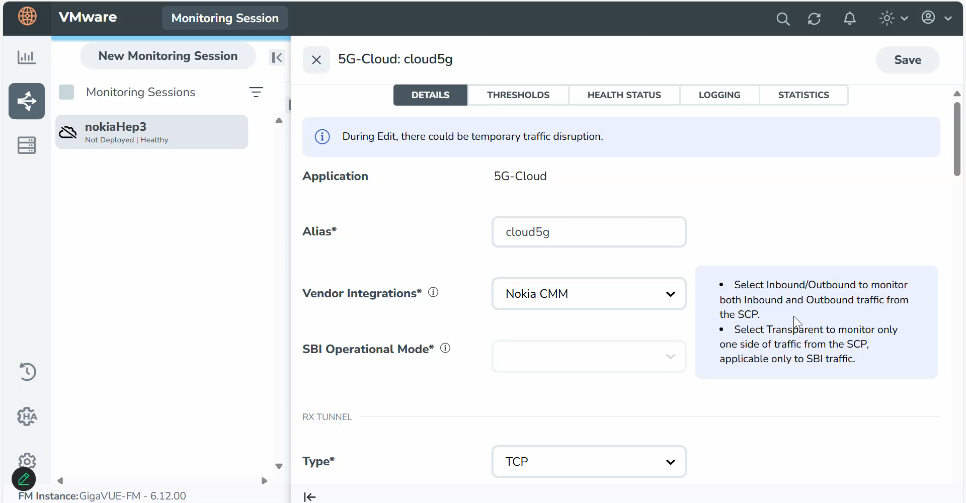
| 2. | On the application quick view, enter or select the required information as described in the Configuration of 5G-Cloud Application for CMM vTAP. |
Note: It is recommended to maintain a 60-90 second delay when undeploying and deploying a Monitoring Session in GigaVUE-FM.
Configuration of 5G-Cloud Application for CMM vTAP
|
Field |
Description |
||||||||||||||||||
|
Application |
The name 5g-Cloud appears by default. |
||||||||||||||||||
|
Alias |
Enter the alias name as cloud5g. |
||||||||||||||||||
|
Vendor Integrations |
From the drop-down list, select Nokia CMM . |
||||||||||||||||||
|
SBI Operational Mode |
The Operational Mode will be grayed out on selecting Nokia CMM/IMS. |
||||||||||||||||||
|
RX Tunnel |
|||||||||||||||||||
|
Type |
Specify the tunnel type. The default is TCP. |
||||||||||||||||||
|
Listening IP |
Specify the tunnel's local listen IP address to receive the packet. |
||||||||||||||||||
|
Listening Port |
Specify the tunnel's local listening port to bind to receive the packet. The application will listen to the traffic coming to the specified port. Enter a value between 1 and 65535. |
||||||||||||||||||
|
Source Port |
Specify the tunnel destination port from where the packets will be sent. Enter a value between 1 and 65535. |
||||||||||||||||||
|
TX Tunnel |
|||||||||||||||||||
|
Type |
Specify the tunnel type. The available tunnel types are:
|
||||||||||||||||||
|
Tool IP |
Specify the remote IP address to send the packet. |
||||||||||||||||||
|
Destination Port |
Specify the tunnel destination port to which the packet will be sent. Enter a value between 1 and 65535. |
||||||||||||||||||
|
Source IP |
Specify the source IP address to use when sending the packet. |
||||||||||||||||||
|
Source Port |
Specify the tunnel source port to bind when sending the packet. Enter a value between 1 and 65535. |
||||||||||||||||||
|
VNI Id (Applicable only when the selected tunnel type is VXLAN) |
Specify the VNI to use for the VXLAN traffic. Enter a value between 0 and 16777215. |
||||||||||||||||||
|
L2GRE Key (Applicable only when the selected tunnel type is L2GRE) |
Specify the key for the L2GRE tunnel type. Enter a value between 0 and 4294967295. |
||||||||||||||||||
|
Advanced Setting |
|||||||||||||||||||
|
Tool MTU |
Specify the tool port MTU. Note: For V Series Node version 6.8.00 and above, the range should be between 1400 and 8800. The default value is 8800. For V Series Node version below 6.8.00, range should be between 1500 and 8800. The default value is 8800. |
||||||||||||||||||
|
Log Directory |
Specify the path to store the log files. |
||||||||||||||||||
|
Log Level |
Select the severity log level of the events from the following options:
|
||||||||||||||||||
|
HEP3 Config |
|||||||||||||||||||
|
Number of Ingress TCP Connections |
Specify the number of concurrent TCP connections VTAP can establish. Enter a value between 128 and 2048. The default value is 1024. |
||||||||||||||||||
|
Ingress TCP Timeout |
Specify the timeout value for an Ingress TCP connection in seconds. Enter a value between 30 and 3600 seconds. The default is 60 seconds. Note: If no packets are received within the configured time, the TCP connection will be terminated due to timeout. |
||||||||||||||||||
|
Number of Egress TCP Flows |
Specify the total number of TCP Flows allocated for tracking non-SBI traffic. Enter a value between:
The default value is 4096. |
||||||||||||||||||
|
Egress TCP Flow Timeout |
Specify the timeout value for an Egress TCP flow in seconds. Enter a value between 30 and 7200 seconds. The default is 900 seconds. Note: If no packets are received within the configured time, the TCP flow will be terminated due to timeout. |
||||||||||||||||||
|
Number of Receiver Threads |
Specify the number of receiver threads for processing incoming packets. Enter a value between 1 and 128. The default value is 8. |
||||||||||||||||||
|
Number of Egress SCTP Flows |
Specify the total number of SCTP flows allocated to track Non-SBI traffic. The valid range is from 128-2000000. The default value is 1024. |
||||||||||||||||||
|
Egress SCTP Flow Timeout |
Specifies the timeout value for an Egress SCTP flow. Valid value range is 30 to 7200 seconds. The default value is 900 seconds. Note: If no packets are received within the configured time, the SCTP flow will be terminated due to timeout. |
||||||||||||||||||
|
mTLS Config |
|||||||||||||||||||
|
mTLS |
Enable or disable mTLS encryption or decryption using the toggle button in mTLS/SSL Monitor Mode. |
||||||||||||||||||
|
mTLS key |
If mTLS encryption is enabled, select the mTLS key alias for the SSL certificate from the drop-down list. To create key alias click on the Add button beside the textbox. For further details refer to Configure SSL Decrypt. |
||||||||||||||||||
|
SCP Config |
|||||||||||||||||||
|
FQDN Mapping |
Select the alias name created for the uploaded FQDN table CSV file from the drop down or add one by clicking on the Add button. |
||||||||||||||||||
|
NF Instance Mapping (Optional) |
Select the alias name created for the uploaded NFID table CSV file from the drop down or add one by clicking on the Add button.. |
||||||||||||||||||
|
User Agent Mapping (Optional) |
Select the alias name created for the uploaded User Agent table CSV file from the drop down or add one by clicking on the Add button.. |
||||||||||||||||||
|
TCP Server Ports |
Specify the TCP server port or port range to allow TCP communication between endpoints. Valid port range is between 1 and 65535. Note: TCP communication is allowed only on the configured ports. |
||||||||||||||||||
|
SCP Advanced Config |
|||||||||||||||||||
|
Packet Capture Level |
Select the packet capture level from the drop-down list:
|
||||||||||||||||||
|
Timestamp |
Select the required timestamp used to save the Egress PCAPs., The available timestamps are:
Note: Timestamp option will be disabled if the Packet capture level is set to None. |
||||||||||||||||||
|
5G-Cloud Log Level |
Select the required 5G-Cloud CSV log level from the drop down list. The default value is None.
|
||||||||||||||||||
Configuration of GvHTTP2 Application for CMM vTAP
|
Field |
Description |
||||||||||||||||||
|
Application |
The name gvhttp2 appears by default. |
||||||||||||||||||
|
Alias |
Enter the alias name as gvhttp2. |
||||||||||||||||||
|
Vendor Integrations |
From the drop-down list, select Nokia CMM. |
||||||||||||||||||
|
HTTP2 Listening IP |
Specify the HTTP2 IP address. The application will listen to the traffic on the specified IP address. |
||||||||||||||||||
|
HTTP2 Listening Port |
Specify the HTTP2 Port. The application will listen to the traffic on the specified port. |
||||||||||||||||||
|
Max Stream |
Specify the maximum number of concurrent streams in one HTTP2 session. Enter a value between 1 and 100. The default value is 100. |
||||||||||||||||||
|
Worker Thread |
Specify the number of parallel threads that can be sued to process the requests. Enter a value between 1 and 16. The default value is 1. |
||||||||||||||||||
|
TX Tunnel |
|||||||||||||||||||
|
Type |
Specify the tunnel type as Nokia HEP3 over TCP from the dropdown for Nokia CMM. |
||||||||||||||||||
|
Source IP |
Specify the source IP address to use when sending the packet. |
||||||||||||||||||
|
Source Port |
Specify the tunnel source port to bind when sending the packet. Enter a value between 1 and 65535. |
||||||||||||||||||
|
Destination IP |
Specify the tunnel destination port to which the packet will be sent. Enter a value between 1 and 65535. |
||||||||||||||||||
|
Destination Port |
Specify the tunnel destination port to which the packet will be sent. Enter a value between 1 and 65535. |
||||||||||||||||||
|
Number of Egress TCP Connections |
Specify the number of concurrent TCP connections GvHTTP2 can establish. Enter the value from 1 to 200. The default value is 4. |
||||||||||||||||||
|
TLS Config |
|||||||||||||||||||
|
TLS |
Enable or disable TLS encryption or decryption using the toggle button. |
||||||||||||||||||
|
Server Private key |
Enter the path where the private key is stored. |
||||||||||||||||||
|
Server Certificate |
Enter the path where the certificate is stored. |
||||||||||||||||||
|
Advanced Setting |
|||||||||||||||||||
|
CSV |
Enable this option to capture all stats counters for GvHTTP2. |
||||||||||||||||||
|
PCAP |
Enable this option to capture the packets at egress. |
||||||||||||||||||
|
Log Directory |
Specify the path to store the log files. |
||||||||||||||||||
|
Log Level |
Select the severity log level of the events from the following options:
|
||||||||||||||||||
Download Logs - 5G-Cloud / GvHTTP2 Application
You can view the log files of a V Series Node or download them as .CSV or .txt files.
To download the log files to a local environment:
| 1. | Go to Traffic > VIRTUAL > select your cloud platform. |
| 2. | Select the required Monitoring Session and go to TRAFFIC PROCESSING tab. On the cloud5g / gvhttp2application, click the  menu button and select Details. Go to LOGGING in the quick view. The Logging page displays the logs currently available. menu button and select Details. Go to LOGGING in the quick view. The Logging page displays the logs currently available. |
| 3. | Select the required Days, Timestamps, File Name, and Type (TextLog and FlowStats) details. |
| 4. | Select the log files to download, and then click Download > Files. The system downloads the selected files to your local environment. |
Add CSV file for IP Mapping
To add the CSV file for IP mapping:
| 1. | Go to Inventory > VIRTUAL > select your cloud platform, and then click Settings > 5G-Apps. The 5G-Apps Configuration page appears. |
| 2. | Click New. Enter the name for the CSV file in the Alias field |
| 3. | From the Type drop-down list, select 5G-Cloud FQDN. |
| 4. | Click Choose File in the FileName field to upload the CSV file into GigaVUE-FM. Add the CSV file containing a valid FQDN ID and a valid IPv4/IPv6 address for IP mapping. |
FQDN Mapping: gigamon@vseries:/var/log/cloud5g_tabledir$ cat FQDN.txt
-
Header details: FQDNid,IngressIP1,IngressIP2,IngressPort,EgressIP,NFType,NFLocation,IMSIP,IMSIntfName,IMSMask,IMSType
-
Example: s25scp01.scp.5gc.mnc003.mcc525.3gppnetwork.org,170.00.13.187,,8080,,SCP,plolp,2000:4000:124:a0d9:ac1:4::,92,303 314 315,sbc
The fields fqdnID and ingressIPAddress1 are mandatory. All other fields are optional.
The fields imsipaddress, imsinterfacename, imsmask and imstype are applicable only when the Integrated solution Vendor is "Nokia HEP3".
| 5. | Click Validate to validate the CSV file. |
| 6. | Click Save to add the CSV file. |


