Configure GRIP Solution
To configure the GRIP solution software:
|
1.
|
On the left navigation pane, go to  > Nodes. Click on the Left Node in which the configuration needs to be done. > Nodes. Click on the Left Node in which the configuration needs to be done. |
|
2.
|
Go to System > Ports > >Ports>All Ports. Select the port that would act as the signaling port and click Edit. |
|
3.
|
Select Enable for Admin. |
|
6.
|
Repeat steps 1 through 5 on the right node to complete the signaling port type configuration. |
|
7.
|
Go to  > Physical > Orchestrated Flows > Inline Flows > Configuration Canvas to create a new Flexible Inline Canvas. > Physical > Orchestrated Flows > Inline Flows > Configuration Canvas to create a new Flexible Inline Canvas. |
|
8.
|
In the displayed canvas, select the device where you want to configure and click the ‘+’ icon next to the Redundancy to create a new entry. |
|
9.
|
Enter a name for the profile in the Alias field.
|
|
10.
|
Click on the Signaling Port field and select the stack port configured in Step 4.
Select Primary for Protection Role. |
|
12.
|
Repeat Steps 8 through 11 for the right node to complete the Redundancy Profile Configuration but select Protection Role as Secondary. |
Configure Synchronization
You must synchronize the configuration of the two GigaVUE nodes involved in the GRIP solution. The configuration items that must be synchronized are as follows:
|
■
|
the signaling ports, as dictated by the signaling link cabling |
|
■
|
the inline networks, as dictated by the network path cabling between the two GigaVUE nodes |
|
■
|
the redundancy profiles. The redundancy profile of each GigaVUE nodes needs to have the same signaling port as well as a redundancy role that is compatible with the redundancy role on the other GigaVUE node. For example, one is configured with the primary role and one is configured with the secondary role. |
In the example below , the configuration is the same on both nodes, except for the protection role (primary or secondary).
Example: Gigamon Resiliency for Inline Protection
Example is an Inline Bypass solution for GRIP using TAP-HC1-G10040 modules on the GigaVUE‑HC1, with copper ports.
First, configure the GigaVUE‑HC1 with the primary role, then configure the GigaVUE‑HC1 with the secondary role. The configuration is the same (is synchronized) on both nodes, except for step 3, in which the protection role (primary or secondary) is specified.
Note that in this example, link fail propagation (LFP) is disabled to reduce inline network recovery time after failover. When a primary to secondary failover occurs and LFP is enabled for copper Inline Bypass links, network service recovery may take several seconds because of Ethernet link renegotiation. Optical links failover faster and typically recover service much faster. For inline networks where only one path is available, this is a consideration. When GRIP is deployed with high availability networks where a second path is present, it is a best practice to leave LFP enabled.
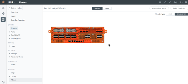
You can use the Chassis page to view the chassis and modules.
Configure Primary Role GigaVUE‑HC1
|
Task
|
Description
|
UI Steps
|
|
|
Configure ports on the TAP-HC0-G100C0 module as passive (in passive mode, relays are closed). Also configure ports, port type (inline-network).
|
|
1.
|
Go to System > Ports > Ports > All Ports. |
|
2.
|
Select a port of the TAP-HC1-G10040 module. |
|
3.
|
Click to open the Ports page. |
|
4.
|
Select Passive for TapTX |
|
6.
|
Repeat steps 2 through 6 for each port on the TAP-HC1-G10040 module |
|
7.
|
Configure Inline Network ports |
a. Select the port.
b. Click Quick Port Editor.
c. Select Inline Network for Type.
Note: You can use the Chassis page to locate the position of the module in the chassis and identify port IDs.
|
|
|
Configure stack port (for signaling port/link) and enable it.
|
|
1.
|
Select the port and click Edit. |
|
2.
|
Select Enable for Admin. |
|
3.
|
Select Stack for Type. |
|
|
|
Create the redundancy profile by giving it a name and configuring parameters for the redundancy profile such as the signaling port and protection role (primary).
|
|
1.
|
Select Physical > Orchestrated Flows > Inline Flows > Configuration Canvas > Redundancy. |
|
3.
|
Enter a name for the profile in the Alias field. For example, RP_001. |
|
4.
|
Click in the Signaling Port field and select the stack port configured in Task 2. |
|
5.
|
Select Primary for Protection Role. |
|
|
|
Configure inline network.
This step associates the redundancy profile to the inline network and also disables link fail propagation on the inline network.
|
Refer to the Configure Inline Network Ports and Inline Networksection for configuration details.
|
|
|
Configure inline tool ports, port type (inline-tool), and administratively enable them.
|
|
1.
|
Select Physical > Orchestrated Flows > Inline Flows > Configuration Canvas > Inline Tool. |
|
2.
|
Select the first port (for example, 1/4/x1) to configure as an inline-tool port. |
|
3.
|
Select Inline Network for Type and select Enable for Admin. |
|
4.
|
Select the second port (for example, 1/4/x2) and repeat steps 3 through 5. |
|
|
|
Configure inline tool and failover action. then enable inline tool.
|
Refer to the Configure Inline Tool Ports and Inline Tools section for configuration details.
|
|
|
Configure map passall, from inline network to inline tool.
Note: When you delete a map on the primary node, irrespective of the inline-network traffic-path, the traffic is switched to the secondary node. The port utilization must be 0% on the primary node and active on the secondary node.
|
Refer to the Configure Inline Network Bundle section for configuration details.
|
Configure Secondary Role GigaVUE‑HC1
|
Task
|
Description
|
UI Steps
|
|
1
|
Configure ports on the TAP-HC0-G100C0 module as passive (in passive mode, relays are closed). Also configure ports, port type (inline-network).
|
|
1.
|
Go to System > Ports > Ports> All Ports. |
|
2.
|
Select a port of the TAP-HC1-G10040 module. |
|
3.
|
Click to open the Ports page. |
|
4.
|
Select Passive for TapTX |
|
6.
|
Repeat steps 2 through 6 for each port on the TAP-HC1-G10040 module |
|
7.
|
Configure Inline Network ports |
|
b.
|
Click Quick Port Editor. |
|
c.
|
Select Inline Network for Type. |
Note: You can use the Chassis page to locate the position of the module in the chassis and identify port IDs.
|
|
2
|
Configure stack port (for signaling port/link) and enable it.
|
|
1.
|
Select the port and click Edit. |
|
2.
|
Select Enable for Admin. |
|
3.
|
Select Stack for Type. |
|
|
3
|
Create the redundancy profile by giving it a name and configuring parameters for the redundancy profile such as the signaling port and protection role (secondary).
|
|
1.
|
Select Physical > Orchestrated Flows > Inline Flows > Configuration Canvas > Redundancy. |
|
3.
|
Enter a name for the profile in the Alias field. For example, RP_001. |
|
4.
|
Click in the Signaling Port field and select the stack port configured in Task 2. |
|
5.
|
Select Secondary for Protection Role. |
|
|
4
|
Configure inline network.
This step associates the redundancy profile to the inline network and also disables link fail propagation on the inline network.
|
Refer to the Configure Inline Network Ports and an Inline Network section for configuration details.
|
|
5
|
Configure inline tool ports, port type (inline-tool), and administratively enable them.
|
|
1.
|
Select Physical > Orchestrated Flows > Inline Flows > Configuration Canvas > Inline Tool. |
|
2.
|
Select the first port (for example, 1/4/x1) to configure as an inline-tool port. |
|
3.
|
Select Inline Network for Type and select Enable for Admin. |
|
4.
|
Select the second port (for example, 1/4/x2) and repeat steps 3 through 5. |
|
|
6
|
Configure inline tool and failover action. then enable inline tool.
|
Refer to theConfigure Inline Tool Ports and Inline Tools section for configuration details.
|
|
7
|
Configure map passall, from inline network to inline tool.
|
Refer to the Configure Inline Network Bundlesection for configuration details.
|
|
8
|
Configure the path of the traffic to the inline tool, disabling physical bypass on the inline network to open the relay on the node with the primary role.
|
Refer to the Configure Inline Network Ports and an Inline Network section for configuration details.
|
Redundancy Control State
To display the Redundancy Control State, go to the Inline Networks page and click on the alias of the Inline Network for which you want to display the redundancy control state. The state is displayed on the Quick View under Configuration.
The below table describes the different Redundancy Control States.
Table 1: Redundancy Control States
|
State
|
Description
|
|
Neutral
|
No redundancy profile is configured.
|
|
Suspended
|
The protection role is configured as suspended.
|
|
Primary Forwarding
|
The protection role is configured as primary. The node is acting in the primary role. Traffic flows through this node.
|
|
Secondary Bypass
|
The protection role is configured as secondary. The node is acting in the secondary role. Traffic bypasses this node.
|
|
Secondary Forwarding
|
The protection role is configured as secondary. The node is acting in the primary role due to a loss of power on the primary node. Traffic flows through this node.
|
How to Use Suspended Role for Maintenance
Use the suspended protection role to perform maintenance activities on the primary and secondary nodes. Maintenance activities include: bringing up a module, shutting down a module, or swapping a module.
For example, to remove a module on one of the GigaVUE‑HC3 nodes (Primary node), use the following steps on that module:
|
1.
|
Select Physical > Orchestrated Flows > Inline Flows > Configuration Canvas > Redundancy. |
|
2.
|
On the Redundancies page, for Protection Role, select suspended, and then clickOK. |
|
3.
|
Once this is configured, the Primary node will be moved to 'Suspended' and the Secondary node will be moved to 'Secondary Forwarding' state.
All the traffic will now be forwarded to the Secondary node and the Inline Tool inspection takes place.
|
|
4.
|
Perform the maintenance activity in Primary node, like bringing up a new module, shutting down a module, swapping the modules, replacing the external inline tool. |
|
5.
|
Once the maintenance is done, revert the Protection Role in Primary Node back to 'primary'.
This will move the Redundancy Control State back to the Primary Forwarding and traffic will start flowing via the Primary Node. |
In case of a maintenance activity (chassis, card, external inline-tool) required in Secondary node follow the below steps:
|
1.
|
Set the Protection Role to 'suspended' in the redundancy profile. |
|
2.
|
Once this is set, the Secondary node will be moved to 'Suspended' and the Primary node will remain in the 'Primary Forwarding' state and will handle the traffic. |
|
3.
|
Do the required maintenance activity in secondary node. |
|
4.
|
Once the maintenance is done, revert the Protection Role in Secondary Node back to 'secondary'. |
|
5.
|
This will move the Redundancy Control State back to the “Secondary Bypass”. |
How to Upgrade GigaVUE Nodes in GRIP Deployment
There are no specific procedures for upgrading the nodes in the GRIP deployment, but we would recommend the below steps to be on the safer side. Even when the upgrading device goes into an issue state, traffic will be inspected in any one of the nodes.
|
■
|
Refer the "Supported Upgrade Path—Standalone Nodes" to know about the order of build version in which the GigaVUE-OS needs to be upgraded. |
|
■
|
Save the configuration and take the backup of both Primary and Secondary node. |
|
■
|
First upgrade the secondary node so that traffic will get inspected in the Primary node. |
|
■
|
Once the Secondary node upgrade gets completed then go for the Primary node upgrade. |
|
■
|
When the Primary node upgrade is in progress, traffic will be inspected in the Secondary node as the failover kicks in, with the help of the signaling port. |
|
■
|
As soon as the Primary node upgrade is complete, the signaling port will come up, and the Primary Node will start inspecting the traffic. |
Troubleshoot
If any of the below issues occur, kindly follow the given steps to troubleshoot the issue.
Signaling Ports Down
1. Check if the power is proper from the optics; if not, try replacing the optics with new ones in a maintenance window
2. If the issue occurs after reloading, check if the maps are configured on the inline network to which the redundancy profile is attached.
3. If maps are not configured, deploying a map will bring up the signaling ports.
4. If a map is available and the signaling ports are still down, contact Gigamon Support for assistance.
Traffic outage in Inline Tool
1. Check if the Redundancy Control State is set to Primary Forwarding in the Primary node or Secondary Forwarding in case traffic is handled in the Secondary Node.
2. Check if the Inline Tool Flex Traffic Path is configured as “Bypass” by mistake. If so, revert to To-Inline-Tool to recover the traffic.
3. Check if the Inline Tool ports are in downstate and failover kicked into tool bypass (the default failover for Inline Tool). If so, correct the optics power, cable, and external Inline Tool faultiness.
4. If the issue persists, contact Gigamon Support for assistance.
Network Traffic Outage
1. Check if any of the Inline Tool’s Flex Traffic Paths is set to “Drop” by mistake. If so, revert the Flex Traffic Path to To-Inline-Tool.
2. Check if any Inline Tool ports are down and failover kicked into tool-drop or network-drop. If so, check the optics power, cable, and External Inline Tool Faultiness and correct the same.
3. Check if the traffic hits the map and drops in any Inline Component ports using 'show port stats port-list <port-alias>.'
4. Try redeploying the Flex Inline Solution from GigaVUE-FM and check if the traffic resumes. If not, contact Gigamon Support for assistance.


