Inline Network and Inline Network Ports
An inline network forms a logical connection between two inline network ports—Port A and Port B—that carry live production traffic. These ports operate at the same speed, use the same medium (fiber or copper), and reside on the same node. Traffic entering one port exits through the other, enabling packets to be inspected or modified by inline tools without disrupting service.
Inline networks can be configured as protected or unprotected, depending on whether failover protection is required:
| Protected inline networks provide high availability by automatically redirecting traffic through a bypass path if a tool or link fails. |
| Unprotected inline networks do not offer automatic failover; traffic stops if a link or tool fails until manual intervention restores service. |
| Mixed inline networks is a combination of protected and unprotected inline networks supported in Inline Bypass solutions (Classic). |
When an inline network connects directly to inline tools, traffic continues to flow based on the configured failover action.
| Drop—All traffic through the inline network is stopped. No packets are exchanged between the inline network ports or with the inline tools. Traffic entering Port A or Port B is dropped. |
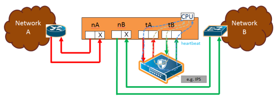
| 1 | Traffic Path of Drop |
| ByPass—Traffic is forwarded directly between the inline network ports, depending on how inline maps are configured: |
| No maps or pass-all maps: All traffic entering Port A is forwarded to Port B, and traffic entering Port B is forwarded to Port A through a logical bypass. |
| Maps with drop conditions: Only traffic that would have been forwarded in To Inline Tool mode is passed through. Packets that were dropped in that mode remain dropped here as well. |
In both cases, no traffic is sent to the inline tools.
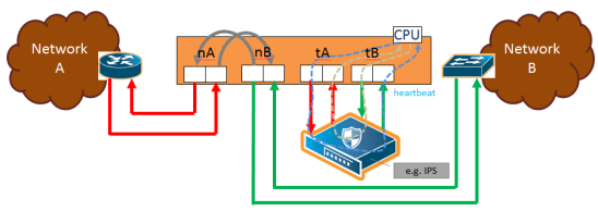
| 2 | Traffic Path of Bypass |
| ByPass with Monitoring—This mode behaves like standard bypass but also sends a copy of the traffic to the inline tools: |
| No maps or pass-all maps: All traffic is forwarded as in bypass mode, while a copy is sent to the inline tools for monitoring. |
| Maps with drop conditions: Only traffic that would not have been dropped in To Inline Tool mode is forwarded and copied for monitoring. |
In both monitoring cases, no packets are received from the inline tools.
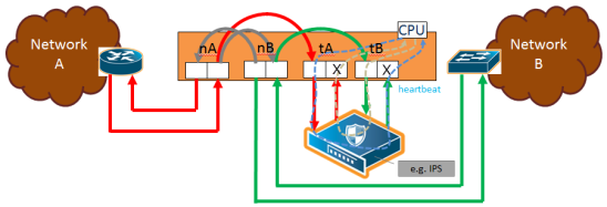
| 3 | Traffic Path of Monitoring |
| To Inline Tool—traffic received at the inline network ports is forwarded according to the following factors: |
| the configured maps between the inline network and the inline tools |
| the failover actions of the inline tool or tools |
| the health state of the inline tool or tools |
The default is Bypass. This avoids any traffic loss when first configuring an unprotected inline network or when disabling physical bypass on a protected inline network.
1 to 4 show the traffic path for a simple inline bypass solution with inline network ports (nA and nB), inline tool ports (tA and tB), and a map passall.
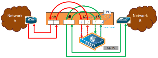
| 4 | Traffic Path of To-Inline-Tool |
Physical Bypass Parameter
One of the parameters of inline networks is physical bypass, which controls the state of the optical protection switch on the bypass combo module or copper TAP module when the module is powered on. The optical protection switch can have one of the following states:
| close—the fiber connected to the side A network port is passively coupled with the fiber connected to the side B port without any transceivers or switching fabric. Therefore, any traffic coming in on these fibers is exchanged between the two inline network ports without being noticed by the system. |
| open—the fiber connected to the inline network ports is coupled through transceivers with the switching fabric that is under software control. Therefore, any traffic coming in on these fibers is subject to the traffic forwarding rules imposed by the current configuration as well as the current state of the inline tools. |
When the bypass combo module or copper TAP modules is powered off, the optical protection switch is always in the close state.
When the bypass combo module or copper TAP modules is powered on, the state of the optical protection switch is as follows:
| the close state if Physical Bypass is set to enable (that is, selected on the configuration page) |
| the open state if physical bypass is set to disable (that is, not selected on the configuration page) |
Physical Bypass is enabled by default.
Note: Physical bypass only applies to protected inline networks.
Resiliency Features
Inline Networks include resiliency mechanisms to handle failures gracefully:
Network Port Link Status Propagation Parameter
Link status propagation controls how the link state is handled for inline network ports. It is enabled by default.
| When enabled, if one side of the inline network fails, the failure is also applied to the other side.For example, if traffic stops on one port and cannot reach the inline tools, the opposite port is also marked down. |
| When the original link comes back up, the opposite side is restored as well. |
| The node will not forward packets to inline tools until both sides of the link are active. |
You can enable or disable this feature by selecting Link Failure Propagation when configuring an inline network port.
Heartbeat Support Between GigaVUE Nodes
Heartbeat packets are lightweight health-check signals exchanged between inline nodes and inline tools. They verify that traffic flows correctly through the inline path. If heartbeats stop, the system assumes a failure and automatically switches traffic to bypass mode, preventing packet loss.
When heartbeats resume, traffic again passes through the inline tools. This feature quickly detects tool or link failures and protects live traffic.
Following figure illustrates an example of a topology with GigaVUE nodes placed at three different layers.
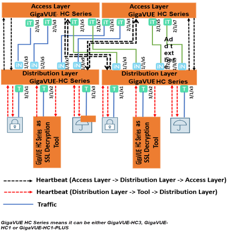
Heartbeats in a Multi-Layer Inline Topology
In a multi-layer setup, heartbeat packets help maintain traffic integrity and support automatic failover.
| The access layer node captures live traffic, sends it to the tool layer for processing, and then returns it to the network. |
| The distribution layer node sits between the access and tool layers, distributing and managing traffic flows. |
In this example, the tool layer node performs TLS/SSL decryption. Heartbeats monitor link health between each layer.
At the access layer, ports facing the distribution layer are configured as inline tool ports. At the distribution layer, ports facing the access layer are configured as inline network ports.
Heartbeat packets flow from the inline tool port pair (access layer) to the inline network port pair (distribution layer). If the distribution layer is in a healthy forwarding state, the heartbeat is returned; otherwise, it is dropped to signal a fault. The same principle applies between the distribution and tool layers.
Here, the distribution layer ports facing the tool layer are inline tool ports, while the tool layer ports facing back are inline network ports.
Heartbeats confirm the availability of both the tool devices and their processing engines.
Display Current State of Inline Bypass Solution
Inline networks, inline tools, and inline maps work together to form an inline bypass solution. The inline bypass solution has an overall state, which can change in response to hardware conditions and user configuration.
Several factors make up the overall state of an inline bypass solution, as follows:
| The physical bypass configuration of the inline network is protected. |
| The inline network configuration, in particular, if physical bypass is enabled or disabled, what traffic path is configured, and if link failure propagation is enabled or disabled. |
| The inline tool configuration, in particular, if the state of the inline tool is enabled or disabled, if there is a heartbeat profile configured and if the heartbeat is enabled or disabled, and what failover actions are configured. |
| The inline tool group configuration, in particular, if the state of the inline tool group is enabled or disabled, what failover mode is configured, what failover action is configured, and what number of minimum healthy tools is configured. |
| The status of the links attached to the inline network ports and inline tool ports. |
Forwarding States and Determining Factors describes each forwarding state and the factors determining that state.
Whenever link failure propagation is configured as false (disabled), the inline network port status reflects the status of the respective far-end ports. Only when link failure propagation is configured as true (enabled) does this behavior change. Refer to the note under the Forwarding states for DISABLED and DISCONNECTED in Forwarding States and Determining Factors.
|
physical-bypass |
traffic-path |
Status of far-end ports connected to inline network ports |
Status of inline tool side |
Description |
|
enable |
drop, bypass, monitoring, or to-inline-tool |
any status |
any status |
Forwarding state—PHYSICAL BYPASS If physical bypass is enabled, all traffic is exchanged directly between side A network and side B network without any monitoring by the GigaVUE node. Only applies to protected inline networks. |
|
disable |
drop |
any status |
any status |
Forwarding state—DISABLED If the inline network is configured with a traffic path of drop, no traffic is exchanged between side A network and side B network because all packets coming to the inline network ports are dropped. Note: If the inline network is configured with link failure propagation set to true (enabled), the status of the inline network ports will be determined by the status of the far-end ports connected to the inline network ports. If both far-end ports are up, then both inline network ports will be up. If any far-end ports are down, then both inline network ports will be down. |
|
disable |
bypass, monitoring, or to-inline-tool |
at least one far-end port is down |
any status |
Forwarding state—DISCONNECTED When one of the inline network ports is down due to a link down caused by a far-end device, no traffic is exchanged between side A network and side B network. Note: If the inline network is configured with link failure propagation enable as true, the status of both inline network ports will be down. That is, if only one inline network port is down, the other will be brought down. |
|
disable |
bypass |
both far-end ports are up |
any status |
Forwarding state—FORCED BYPASS If the inline network is configured with a traffic path of bypass, all traffic that would not have been dropped when the traffic path is set to to-inline-tool is exchanged directly between side A network and side B network through the switching fabric. |
|
disable |
monitoring |
both far-end ports are up |
any status |
Forwarding state—FORCED BYPASS WITH MONITORING If the inline network is configured with a traffic path of monitoring, all traffic that would not have been dropped when the traffic path is set to to-inline-tool is exchanged directly between side A network and side B network through the switching fabric. If there is any inline map configured for the inline network, a copy of the respective traffic is directed to the respective inline tools according to the configured inline maps. |
|
disable |
to-inline-tool |
both far-end ports are up |
all inline tools involved in the inline bypass solution are operating as expected |
Forwarding state—NORMAL If all inline tools involved in the inline bypass solution are enabled, all inline tool ports are up, and the inline tools operating with heartbeat protocol enabled have a heartbeat status of up, traffic flows as desired according to the configuration of the inline maps. Note: If there are no inline maps, setting the traffic path of a protected fiber inline network to to-inline-tool results in a NORMAL forwarding state, but the traffic sent to the source inline network ports will be dropped because there are no inline maps specifying destination tool ports to which to forward the traffic.
|
|
disable |
to-inline-tool |
both far-end ports are up |
at least one inline tool involved in the inline bypass solution is disabled or associated with any inline tool port that is down or associated with the heartbeat protocol in a down state |
Forwarding state—FAILURE-INTRODUCED BYPASS All traffic is exchanged directly between side A network and side B network through the switching fabric as a result of an inline tool port failure or heartbeat failure or inline tool being disabled that led to the network-level bypass due to the configured failover actions. |
|
disable |
to-inline-tool |
both far-end ports are up |
at least one inline tool involved in the inline bypass solution is disabled or associated with any inline tool port that is down or associated with the heartbeat protocol in a down state |
Forwarding state—FAILURE-INTRODUCED DROP No traffic is exchanged between side A network and side B network. All packets coming to the inline network ports are dropped as a result of an inline tool port failure or heartbeat failure or inline tool being disabled that led to the network-level drop due to the configured failover actions. |
|
disable |
to-inline-tool |
both far-end ports are up |
at least one inline tool involved in the inline bypass solution is disabled or associated with any inline tool port that is down or associated with the heartbeat protocol in a down state |
Forwarding state—NETWORK PORTS FORCED DOWN No traffic is exchanged between side A network and side B network. The inline network ports are forced down as a result of an inline tool port failure or heartbeat failure or inline tool being disabled that led to the network ports being forced down due to the configured failover actions. |
|
disable |
to-inline-tool |
both far-end ports are up |
at least one inline tool involved in the inline bypass solution is disabled or associated with any inline tool port that is down or associated with the heartbeat protocol in a down state |
Forwarding state—ABNORMAL Any condition of the inline bypass solution that does not meet the criteria of the forwarding states listed in this table. At least one inline tool passes traffic as desired. There are many scenarios that can lead to the abnormal forwarding state, for example, when one inline tool member of an inline tool group has failed, but the number of remaining healthy tools is still above the minimum required number of healthy tools. |


