CLI Configuration Example
The figure1 Leaf Spine Topology shows the topology for this configuration example.
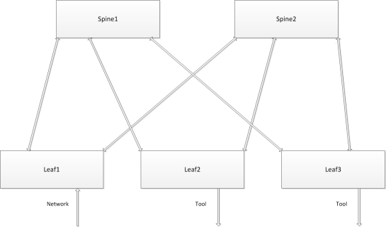
| 1 | Leaf Spine Topology |
It is assumed that the out-of-band cluster has already been configured prior to this configuration example.
One of the nodes in the cluster is the leader. The configuration steps are done from the leader node.
The1, incoming traffic arrives on Leaf1. Outgoing traffic is sent to tools on Leaf2 and Leaf3. On the right side, the GigaStream between Leaf3 and Spine2 have multiple ports, forming a larger trunk.
The abbreviations of the aliases used in this configuration example are as follows:
| l1, l2, and l3 refer to leaf1, leaf2, and leaf3 nodes |
| s1 and s2 refer to spine1 and spine2 nodes |
| gs refers to GigaStream |
| sl refers to stack link |
The following are the stack GigaStream. There are 12 in all, as follows:
| leaf1, spine1 GigaStream (l1s1gs) |
| leaf1, spine2 GigaStream (l1s2gs) |
| leaf2, spine1 GigaStream (l2s1gs) |
| leaf2, spine2 GigaStream (l2s2gs) |
| leaf3, spine1 GigaStream (l3s1gs) |
| leaf3, spine2 GigaStream (l3s2gs) |
| spine1, leaf1 GigaStream (s1l1gs) |
| spine1, leaf2 GigaStream (s1l2gs) |
| spine1, leaf3 GigaStream (s1l3gs) |
| spine2, leaf1 GigaStream (s2l1gs) |
| spine2, leaf2 GigaStream (s2l2gs) |
| spine2, leaf3 GigaStream (s2l3gs) |
The following are the spine links. There are 3 in all, as follows:
| leaf1spine (l1spine), consisting of l1s1gs and l1s2gs |
| leaf2spine (l2spine), consisting of l2s1gs and l2s2gs |
| leaf3spine (l3spine), consisting of l3s1gs and l3s2gs |
The following are the stack links. There are 6 in all, as follows:
| leaf1, spine1 stack link (l1s1sl), between l1s1gs and s1l1gs |
| leaf2, spine1 stack link (l2s1sl), between l2s1gs and s1l2gs |
| leaf3, spine1 stack link (l3s1sl), between l3s1gs and s1l3gs |
| leaf1, spine2 stack link (l1s2sl), between l1s2gs and s2l1gs |
| leaf2, spine2 stack link (l2s2sl), between l2s2gs and s2l2gs |
| leaf3, spine2 stack link (l3s2sl), between l3s2gs and s2l3gs |
CLI Configuration Commands
Use the following CLI commands to configure the multi-path leaf and spine architecture of the nodes in a cluster environment, in the following order:
| Define stack GigaStream. |
| Define spine links. |
| Define stack links. |
|
Step |
Description |
Command |
|||
|
Configure five stack ports. |
(config) # port <port-list> type stack (config) # port <port-list> param admin enable |
|||
|
Configure network and tool ports. |
(config) # port <port-id> type network (config) # port <port-id> type tool |
|||
|
Configure stack GigaStream. In this example, 12 GigaStreams have been configured. |
(config) # gigastream alias <gigastream-alias> port-list <port-list> |
|||
|
Configure spine links. There are 3 spine links required for this configuration example. The spine links are located at the leaf nodes. |
(config) # spine-link <spine-link alias> port-list <port-list> |
|||
|
Configure stack links. There are 6 stack links required for this configuration example. |
(config) # stack-link <stack-link alias> between gigastreams <gigastream alias> and <gigastream alias> |
|||
|
Configure a map, from a network port to tool ports. |
(config) # map alias <map alias> (config map alias map1) # from <port-list> (config map alias map1) # to <port-list> (config map alias map1) # rule add pass protocol tcp (config map alias map1) # exit (config) # |
Note: Configure ports of same speed in the Stack GigaStream.


