GigaVUE-TA200 Chassis
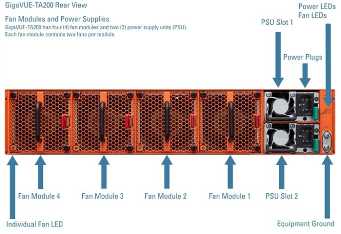
This section describes the physical layout of the GigaVUE-TA200 chassis, including a description of all ports and connectors. The GigaVUE-TA200 chassis consists of a 2RU, rack-mountable, 19”-wide chassis with management, network, and tool ports at the front and power connections and fans at the rear. Figure 7: The GigaVUE-TA200 Chassis Front View shows the ports at the front of the GigaVUE-TA200 chassis. Refer to Table 1: GigaVUE-TA200 Ports for a description of each of the ports. Figure 8: The GigaVUE-TA200 Chassis Rear View shows the fan modules and power supply units at the rear of the GigaVUE-TA200 chassis. Refer to Chassis Cooling for information on fans and temperature monitoring.
The GigaVUE-TA200 provides sixty-four ports, supporting high-density aggregation. Depending on the transceiver, QSFP+ or QSFP28, the ports run at speeds of either 40Gb or 100Gb. With QSFP28 SR4 transceivers, a 100Gb port can be broken out into four 25Gb ports, called 4x25G mode. With 40G SR4, 40Gb ESR4 and PLR4 QSFP+ transceivers (QSF-502, QSF-507, and QSF-506, respectively), a 40Gb port can be broken out into four 10Gb ports, called 4x10G mode.
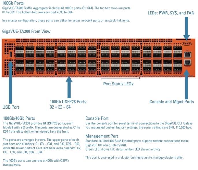
Figure 7: The GigaVUE-TA200 Chassis Front View
|
Port |
Description |
|
Mgmt |
Use the Mgmt port for remote configuration of the GigaVUE-TA200 Traffic Aggregator over a 10/100/1000 Ethernet network. |
|
Console |
Use the console port for local configuration of the GigaVUE-TA200 Traffic Aggregator over a serial connection. |
|
USB |
The USB port is not supported in software version 5.3. |
|
Ports c1..c64 or c1x1..c1x4 to |
GigaVUE-TA200 includes 64 100Gb ports (c1..c64). These ports also support 40Gb speeds. The 40Gb/100Gb ports on the GigaVUE-TA200 can be broken out into four 10Gb/25Gb ports, called subports. The subports will all have the same speed (10Gb/25Gb). Subports will have x1 to x4 appended to their port ID, for example, 1/1/c2x1. Port breakout is supported on the first 32 ports (ports c1 .. c32). On the first and last 10 ports of the top two rows (ports c1 .. c10 and c23 .. c32), there is no impact on the lower ports. When you break out the middle 12 ports, there is an impact on the lower ports. Refer to “Ports c11..c22” below. For details on 4x25G port breakout mode, refer to Configure the Port Mode. Once a 40Gb/100Gb port has been configured to operate as four 10Gb/25Gb ports, cable it to an optical patch panel or breakout panel, such as PNL-M341, which takes input from the GigaVUE-TA200 and splits it to four independent 10Gb/25Gb output ports. Refer to Breakout Panels. |
|
Ports c11..c22 c11x1..c11x4 to |
When you use ports c11 .. c22 for port breakout, there is an impact on the ports in the lower row of the GigaVUE-TA200. In the following list, ensure that the ports on the right do not have any configurations when you use the port on the left for port breakout: c11 à c33, c34 c12 à c40, c41, c42 c13 à c43, c44, c45 c14 à c35, c36 c15 à c37, c38, c39 c16 à c46, c47, c48 c17 à c49, c50 c18 à c52, c57, c59 c19 à c60, c61, c62 c20 à c51, c53 c21 à c54, c55, c56 c22 à c58, c63, c64 For example, if you use c11 for port breakout, ports c33 and c34 will be inactive. Ensure that the ports on the right are disabled. You will receive an error message, if you try, for example, to breakout port c11 when c33 or c34 are enabled. |
|
Transceivers |
For details about the supported transceiver, cable type, and connectivity specifications, refer to “GigaVUE-OS Compatibility and Interoperability Matrix”. |