GigaSMART MPLS Traffic Performance Enhancement
GigaSMART MPLS Traffic Performance Enhancement does not require a separate license.
The GigaSMART MPLS traffic performance enhancement provides a method to improve GigaSMART packet processing for MPLS traffic and other traffic having Layer 2 encapsulation, such as L2GRE or VNTag. This type of traffic has a header in the packet between the MAC address and the IP address. Figure 829: MPLS Header Between MAC and IP Address in Packet shows the MPLS example.

Figure 829: MPLS Header Between MAC and IP Address in Packet
The GigaSMART processor is able to identify IP flows if there is only the MAC address and no other header in the packet before the IP address or if the only header before the IP address is VLAN. Without this enhancement, the GigaSMART processor cannot identify IP flows if there are MPLS headers or Layer 2 encapsulation other than VLAN before the IP address.
Performance is impacted if the GigaSMART processor cannot use the IP source and destination (ipsrc, ipdst) to identify flows. This enhancement provides another method to identify flows. Using a flow mask, you select the portion of the packet for flow identification.
The flow mask consists of an offset and a length, in bytes. Use the offset to specify the number of bytes from the beginning of the packet to the start of the mask within the packet. Use the length to specify the number of bytes, following the offset, to mask within the packet. The length identifies the traffic flow.
Both the offset and the length are variable; however, the offset plus the length cannot be greater than 112 bytes.
A default mask is provided with an offset of 14 bytes and a length of 28 bytes.
To configure the MPLS traffic performance enhancement, do the following:
| 1. | From the device view, select GigaSMART > GigaSMART Group > GigaSMART Groups. |
| 2. | Click New to create a new GigaSMART group or Edit to modify an existing one. |
| 3. | Go to Flow Mask under GigaSMART Parameters and select Enable. |
| 4. | Enter the offset and length in the Offset (bytes) and Length (bytes) fields. |
If you do not enter any values in these fields, the default offset and length is used.
| 5. | Click Save. |
Refer to the following sections for examples:
| • | Flow Masking Example 1 |
| • | Flow Masking Example 2 |
Flow Masking Example 1
In Example 1 packets are expected to have two MPLS labels before the IP header, and no VLAN tag between the MAC and MPLS headers. IP addresses will be used to identify the flows.
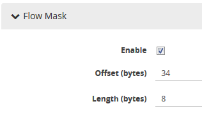
The offset will be the sum of the following: 14 bytes for the MAC address + 8 bytes for the MPLS headers +12 bytes offset from the beginning of the IP header = 34 bytes.
The length will be the sum of the following: 4 bytes for ipsrc + 4 bytes for ipdst = 8 bytes.
To configure Example 1, do the following:
| 1. | From the device view, select GigaSMART > GigaSMART Groups > GigaSMART Groups. |
| 2. | Click New to create a new GigaSMART Group or Edit to modify an exiting one. |
| 3. | Under GigaSMART Parameters, go to Flow Mask and select Enable. |
| 4. | Enter 34 in the Offset (bytes) field and 8 in the Length (bytes) field as shown in the following figure |

| 5. | Click Save. |
Flow Masking Example 2
In Example 2, packets are expected to have one VLAN tag and two MPLS labels before the IP header. IP addresses will be used to identify the flows.
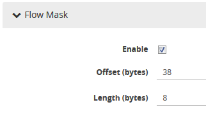
The offset will be the sum of the following: 14 bytes for the MAC address + 4 bytes for the VLAN tag + 8 bytes for the MPLS headers +12 bytes offset from the beginning of the IP header = 38 bytes.
The length will be the sum of the following: 4 bytes for ipsrc + 4 bytes for ipdst = 8 bytes.
To configure Example 2, do the following:
To configure Example 1, do the following:
| 1. | From the device view, select GigaSMART > GS Groups > GS Groups. |
| 2. | Click New to create a new GigaSMART Group or Edit to modify an exiting one. |
| 3. | Click Enable under GS Params Flow Mask. |
| 4. | Enter 38 in the Offset (bytes) field and 8 in the Length (bytes) field as shown in the following figure. |

| 5. | Click Save. |


