Why PTP?
PTP is a time synchronization protocol defined in IEEE 1588 version 2 (ITU-T G.8275.1) for devices across a network. Using PTP, you can synchronize distributed clocks with nanoseconds accuracy. The clocks in the PTP-enabled devices follow a source-receiver hierarchy. The receivers are synchronized to their sources. The top-level source is called the primary source. The primary source clock is synchronized with a Global Positioning System (GPS).
The source will send a synchronization message to the receiver. In turn, the receiver sends a delay request to the source and the source reverts with a delay response. Thus, the delay is measured and the clock of the receiver is synchronized with the source. This is also called as the one-step synchronization.
PTP-enabled devices can have the following clock modes:
| Ordinary clock— A clock that has only one PTP-enabled port and maintains the timescale used in the domain. It can serve either as a source or a receiver. |
| Boundary clock—A clock that has multiple PTP-enabled ports and maintains the timescale used in the domain. The ports can serve either as a source or a receiver. |
The Best Master Clock (BMC) algorithm that is run on every clock is used to determine the best clock in a distributed network. The algorithm compares the attributes from two different clocks to determine the data that describes the better clock. The algorithm is used to determine which of the clocks described in the announce messages received by a local clock port is the best clock. It is also used to determine whether a newly discovered clock, which is a foreign source, is better than a local clock. For more information on the BMC algorithm, refer to the ITU-T G.8275.1 standard.
PTP Deployment shows an example of a distributed network, in which the PTP-enabled devices work in a source-receiver hierarchy.
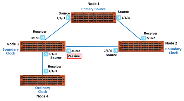
| 1 | PTP Deployment |
In this example, you have node 1, which is a top-level device that acts as a primary source. This device is linked to node 2 and node 3, which are boundary clocks. Node 3, in turn is linked to node 4, which is an ordinary clock. All these devices are synchronized in a source-receiver hierarchy. Node 3 is synchronized with the primary source through the network port, 3/1/c1, which acts as a receiver. The other port 3/1/c2 on node 3 is in passive state. When the link between the primary source and node 3 goes down, the network port, 3/1/c2, which was in the passive state transitions to receiver state. This will ensure that node 3 as well as node 4 remain synchronized with the primary source through node 2 (refer to 2).
![]()
| 2 | PTP State Transition |
Limitations
The following restrictions are applicable for the above feature:
| A two step PTP clock mode is not supported. |
| One step GigaVUE-TA200 clock cannot synchronize time with a two step PTP Primary Source. |
Synchronization of the PTP and Local System Clock
From 5.13.01 version, PTP clock will be synchronized with the local system clock to provide accurate UTC timestamping. This process takes over in the absence of a Primary source clock and when the node is acting as a source clock. In this scenario, if there is a change in the local system clock due to NTP or manual configuration the same change will be synced to the PTP clock.
Recommendation: All local clocks that are running on PTP domain should share the same time value. This can be ensured through NTP server.


