Viewing the PTP Configuration on a Port
After you enable PTP on a network port, you can view the port’s clock state and other details of PTP configuration in the PTP Port State page. To view the page, go to Settings > Date and Time > PTP Port State. 1 shows the PTP configuration details.
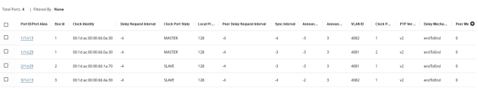
| 1 | PTP Port State |
Following table lists the PTP port states and their descriptions:
|
PTP Port State |
Description |
|||||||||||||||||||||||||||
|
Port ID/Port Alias |
The identifier of the port on which PTP is enabled. |
|||||||||||||||||||||||||||
|
Box ID |
The box identifier of the device. |
|||||||||||||||||||||||||||
|
Clock Identity |
The clock identity of the device. It is a 64-bit global identifier (EUI-64) as defined by the IEEE standard. |
|||||||||||||||||||||||||||
|
Delay Request Interval |
The minimum interval allowed between PTP delay request messages when the port is in the source state. |
|||||||||||||||||||||||||||
|
Clock Port State |
Based on the role defined for the port, the clock state will be Master or Slave. Following are the clock port states:
|
|||||||||||||||||||||||||||
|
Local Priority |
The priority value used to determine the PTP source when the BMC algorithm chooses more than one clock as the source. This value overrides the default criteria for the BMC selection. The clock with the lower priority value will be selected. The valid range is between 1 and 255. For example, on a particular device, the local priority of a port is compared with the local priority of the clock. Based on the following criteria, thesource is determined:
|
|||||||||||||||||||||||||||
|
Peer Delay Request Interval |
The minimum interval allowed between PTP delay request messages between peer ports. |
|||||||||||||||||||||||||||
|
Sync Interval |
The time interval between PTP synchronization messages on the port. |
|||||||||||||||||||||||||||
|
Announce Interval |
The time interval, in log seconds, between PTP announce messages in the port. |
|||||||||||||||||||||||||||
|
Announce Receipt Timeout |
The maximum number of consecutive announce messages that the port fails to receive. When the number of consecutive announce messages that the port failed to receive is greater than the value specified in this field, the port’s clock state changes to source. |
|||||||||||||||||||||||||||
|
VLAN ID |
The identifier of the VLAN interface. |
|||||||||||||||||||||||||||
|
Clock Port ID |
The port identifier assigned by the PTP clock. |
|||||||||||||||||||||||||||
|
PTP Version |
The PTP version that is enabled in the port. |
|||||||||||||||||||||||||||
|
Delay Mechanism |
The mechanism used to determine the delay between a source and a receiver. Following is the delay mechanism that Gigamon supports:
|
|||||||||||||||||||||||||||
|
Peer Mean Path Delay |
Reserved for future use. |


