Ports
The Ports tab lets you select the All Ports and Ports Discovery pages. You can also control which ports display.
All Ports
The All Ports page displays when you select All Ports. The Ports page shows a table with detailed information about each port ID on a specific device. Only the GigaVUE HC Series and GigaVUE TA Series devices are presented in the Port Page view as shown in Table 2: Descriptions of Ports Page Columns. You can control which ports display on the page by selecting a set of filters or configure the ports through the Quick Port Editor or selecting Edit for a selected port. For details about filtering ports, refer to Port List Filter. For details about the Quick Port Editor, refer to Quick Port Editor.
| 1 | Ports Page |
The port type determines which columns are populated with data in the table. The columns are populated as follows:
| Engine ports populate the Port ID, Type, and Link columns. |
| Network ports populate the Port ID, Alias, Type, Speed, Admin Enabled, Link Status, Transceiver Type, Utilization, Port Filter, and Discovery Protocol. |
| Tool port populate the Port ID, Alias, Type, Speed, Admin Enabled, Link Status, Transceiver Type, Utilization, Port Filter, and Discovery Protocol. |
| Stack port populates Port ID, Alias, Type, Admin Enable, Link Status, Utilization, Port Filter, and Discovery Protocol. |
| Hybrid port populates Port ID, Alias, Type, Admin Enable, Link Status, Utilization, Port Filter, and Discovery Protocol. |
| Circuit port populates Port ID, Alias, Type, Admin Enable, Link Status, Utilization, Port Filter, and Discovery Protocol. |
| Inline Network port Port ID, Alias, Type, Admin Enable, Link Status, Utilization, Port Filter, and Discovery Protocol. |
| Inline Tool port Port ID, Alias, Type, Admin Enable, Link Status, Utilization, Port Filter, and Discovery Protocol. |
Note: Not all port types are supported on all platforms. Inline network and inline tool ports are supported on GigaVUE HC Series nodes, GigaVUE-TA25, GigaVUE‑TA25E and GigaVUE-TA200, GigaVUE‑TA200E.
Table 2: Descriptions of Ports Page Columns provides descriptions of the columns on the ports page.
| Column | Description | ||||||||||||
|---|---|---|---|---|---|---|---|---|---|---|---|---|---|
|
Port ID |
The port number is in <box ID>/<slot ID>/<port_ D> format in the CLI and In a standalone (default) configuration, box ID is always designated as 1 but can be changed through the CLI (it cannot be changed through H-VUE ). In a cluster configuration, the box ID can vary. |
||||||||||||
|
Alias |
Alias name of the port, if any. |
||||||||||||
|
Status |
Health status of the port. Note: When a ports administrative status changes from 'enabled' to 'disabled', the health status of the administratively disabled ports remains in Green. However, the health status of administratively disabled port is indicated as NA if Exclusion Rules are enabled for the ports that are admin disabled in the Alarms Page. Refer to the 'Manage Alarms' section in the GigaVUE Administration Guide for more details. |
||||||||||||
|
Type |
List the type of port such as network, tool, stack, inline network, inline tool, circuit, or hybrid. You can set the port type through the Quick Port Editor or selecting the port on the Port page and clicking Edit. The port type is set by selecting the type in the Type field. |
||||||||||||
|
Speed |
Current setting for the port’s speed. |
||||||||||||
|
Admin |
Indicates whether the port is administratively enabled or disabled. |
||||||||||||
|
Force Link Up |
Indicates the ‘force link up’ setting for the port. When enabled, this option forces connection on the optical port. |
||||||||||||
|
Ude |
Indicates whether the port is enabled for unidirectional (Ude) or bidirectional traffic. Enabled means unidirectional; Disabled means bidirectional. |
||||||||||||
|
FEC |
Configures forward error correction (FEC) on the port to ensure error-free traffic over long distance. The values are:
This option is available only on 25Gb and 100Gb transceivers. |
||||||||||||
|
Link Status |
The current status of the link connected to the port, either port link up or port link down. |
||||||||||||
|
Transceiver Type |
The type of transceiver installed in this port. |
||||||||||||
|
SFP Power |
SFP power for copper transceivers Note: When a new device is added to GigaVUE-FM, it takes one stats cycle for the SFP power value to be reflected in the GigaVUE-FM GUI. |
||||||||||||
|
Port Filter |
Indicates if the egress port filter (tool, hybrid, circuit, and inline network), is associated with this port. |
||||||||||||
|
Discovery Protocol |
Protocol used to discover neighboring nodes using CDP or LLDP. This feature is available for network, tool and circuit ports. |
||||||||||||
|
Box Hostname |
Host name of the device |
||||||||||||
|
Gigamon Discovery |
Indicates if Gigamon Discovery protocol is enabled |
||||||||||||
|
Tags |
Tag associated with the port. |
||||||||||||
Port Quick View
The Quick View for ports displays when you click on a row in the Ports page to quickly get more information about a specific port. The quick view shows the port properties, statistics information on receiving (Rx) and/or Transmitting (Tx) ports and alarms information. The quick view also shows a graphical representation of port statistics. Refer to 3 for an example.
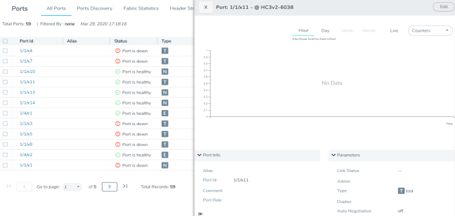
| 3 | Ports Quick View |
Port List Filter
The ports that display on the Ports page can be filtered so that only ports that meet certain criteria display on the page, such as port type and admin status. To filter the ports, select Filter. This opens the Filter view shown in 4 where you can specify how to filter ports displayed on the Ports page.
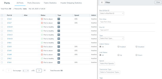
| 4 | Port List Filter |
The criteria that you can use to filter the port list is as follows:
|
Criteria |
Description |
||||||||||||||||||||||||
|
Box/Slot ID |
Display only those ports that match the specified box and slot IDs. |
||||||||||||||||||||||||
|
Port Alias |
Display port with the specified alias. |
||||||||||||||||||||||||
|
Port ID |
Display ports with specified number in the port ID. For example, if you specify 3 the result will also display ports that include the number 3, 13, 23, 30, and so on. |
||||||||||||||||||||||||
|
Type |
Display ports with the specified port type. Select one of the following:
|
||||||||||||||||||||||||
|
Admin Status |
Display ports based on their current admin status. The possible selections are: All — display ports with a status of Enabled or Disabled. This is the default. Enabled — display ports with admin enabled Disabled — display ports with admin disabled |
||||||||||||||||||||||||
|
Link Status |
Display ports based on their current link status: The possible selections are: All — display ports with a status of Up or Down. This is the default. Enabled — display ports with a link status of up. Disabled — display ports with a link status of down. |
||||||||||||||||||||||||
|
Speed |
Display ports with the selected port speed. The port speeds available depend on the node. |
||||||||||||||||||||||||
|
Transceiver Type |
Display ports with the selected transceiver type. The transceivers available selection depend on the type of transceivers connected to the ports. |
||||||||||||||||||||||||
|
Tags |
Display ports associated with the selected tag key and tag value. |
To filter the ports, enter the information to use for filtering the ports and select the radio buttons. For example, in 5, the filters selected are Network Type and Admin Status Enabled. Click the Clear button to remove the filter selections.
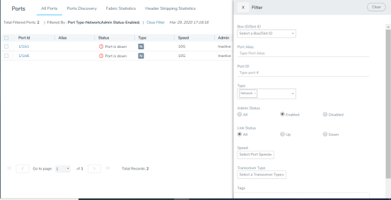
| 5 | Filtering by Network Port Type and Admin Status Enabled |
After the filter is applied, the Ports page displays only the ports that correspond to the selected filters and shows the total number of ports that meet the criteria. To clear the filters, select Clear Filter. 6 shows the Port pages with two ports that correspond to the current filters: Network Type and Admin Status Enabled.
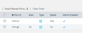
| 6 | Filtered Ports List |
Quick Port Editor
From the Ports page, you can open the Port Type Editor to quickly change the port types in a chassis. To set the port type for ports in a chassis, do the following:
| 1. | Click Quick Port Editor. |
| 2. | For each port on which you want to set the port type, select the type from the drop-down list. In 7, port 1/1/x9 is being changed from a network port to at tool port. |
To find a specific port, you can use the Quick Search to find a specific port by entering the port ID or alias in the Quick search field.
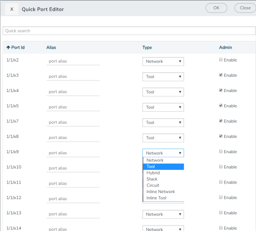
| 7 | Port Type Selection |
| 3. | To enable the port, select Enable. |
| 4. | Click OK. |
Each port can also be assigned an alias. Any port types set in the CLI or through the GigaVUE-FM APIs are reflected on this page. For more information, refer to Port Aliases for port aliases and to the GigaVUE-FM REST API Reference in GigaVUE-FM User's Guide and the GigaVUE-FM Reference for APIs.
Configure Ports
From the Ports page, you can either configure or edit a specific port by selecting a port and clicking the Edit button on the Ports page or on the Quick Port Editor. Table 8: Port Configuration Options describes the options on the configuration page.
| Field | Description | |||||||||
|
Alias |
The alias configured for this port, if any. Aliases can be used in place of the numerical bid/sid/pid identifier required in many packet distribution commands in the CLI. For example, instead of configuring a connection between, say, 1/1/x1 and 1/2/x4, you could connect Gb_In to Stream-to-Disk. Note that aliases can only be applied to single ports. They cannot be applied to groups of ports. Port alias can be up to 128 characters long including special characters. Aliases are case sensitive. |
|||||||||
|
Admin |
Check to enable the port. |
|||||||||
|
Type |
Specifies whether the port is configured as an Inline Network port, Inline Tool port, Network port, Tool port, Stack port, Circuit port, or Hybrid port. |
|||||||||
|
Speed |
Specifies the speed for the selected port. For copper ports, you can click to change the speed as long as Auto Negotiation is disabled. |
|||||||||
|
Duplex |
Specifies the port's duplex configuration. Only full duplex is supported. Starting in software version 5.2, half duplex support is removed from all GigaVUE nodes. If half duplex was configured in a previous software version, it will remain intact following the upgrade to 5.2 or higher release. Update to full duplex, if required. |
|||||||||
|
Auto Negotiation |
Select to enable auto-negotiation for the selected port. When auto-negotiation is enabled, duplex and speed settings are ignored. They are set through auto-negotiation. For 1Gb fiber ports, auto-negotiation is not supported on Gigamon Platforms.. |
|||||||||
|
Force Link Up |
When enabled, this option forces connection on an optical port. Use this option when an optical GigaPORT tool port is connected to a legacy optical tool that does not transmit light. This option is not available for 10Gb capable ports with a 1Gb SFP installed. |
|||||||||
|
Ude |
When selected, this option indicates the port is unidirectional (UDE). When deselected (disabled), the port is bidirectional. UDE is enabled by default. Note: This option is available for GigaVUE‑HC2 (CCv2), GigaVUE‑HC3, GigaVUE-TA100, GigaVUE-TA200, GigaVUE-TA25 and GigaVUE-TA400 platforms with 100Gb BiDi (QSB-512) transceiver. If used with passive taps, ports used for monitoring should be set to Network port with UDE enabled. Important:If you clear the UDE check box, the laser will start to transmit, which may affect the remote connectivity. |
|||||||||
|
FEC |
Configures forward error correction (FEC) on the port to ensure error-free traffic over long distance. The values are: CL91—Enables FEC on the port. CL74— Enables FEC on the port . CL108 — Enables FEC on the port for GigaVUE‑TA25. OFF—Disables FEC on the port. This option is available only on 25Gb and 100Gb transceivers. |
|||||||||
|
Timestamp |
Use the timestamp options when a GigaPORT-X12-TS line card is installed. For details about the GigaPORT-X12-TS line card, refer to the GigaVUE-OS CLI Reference Guide. The timestamp options are as following: Append Ingress—Use this option to add a timestamp to ingress packets a GigaPORT-X12-TS ports. This applies to ports x1..x12 when configured as network ports. Strip Egress—Use this option to strip timestamps from egress packets. Source ID Egress—Use this option to specify a custom source ID to be included in the timestamp appended by the GigaPORT-X12-TS. The source ID identifies the ingress port on the GigaVUE H Series node where the timestamped packet arrived. The timestamp always includes a source ID. If you do not specify a custom value, the GigaPORT-X12-TS generates one automatically using the following formula: (Box ID * 2048) + (Slot ID * 256) + Port Number Important: Only apply the Strip Egress option to packets with time stamps appended. The strip egress feature strips the last 14 bytes of each packet regardless of whether a timestamp has been added. |
|||||||||
|
VLAN Tag |
Use VLAN tags to identify, differentiate, or track incoming sources of traffic. When the traffic reaches the tools or the maps, you can filter on the VLAN tags for the corresponding ports you want to measure. The port must be a network or inline-network or hybrid type of port. Ingress port VLAN tagging is supported for IPv4 and IPv6 packet types, including non-tagged packets, tagged packets, and Q-in-Q packets. Ingress port VLAN tagging is not supported on inline network ports, hybrid ports, or on network ports that are connected via port-pairs. The same VLAN tag can be assigned to multiple network ports. However, each port can only have one VLAN tag. VLAN tagging is supported in a cluster.
VLAN tags are only available on network ports. Note: On GigaVUE-TA25 , ingress VLAN tagging is not supported on network ports associated with GSOP maps and GSOP maps are not supported on network ports configured with ingress vlan tag. This limitation is not applicable with E-tag mode. |
|||||||||
|
Port Discovery |
Select to enable discovery of neighbors associated with the port. Neighbor discovery is only available on network ports |
|||||||||
|
Discovery Protocols |
When port discovery is enabled, use the Discovery Protocol options to set up CDP or LLDP or both (All) on the port. The results are shown on the Ports Discovery page. |
|||||||||
|
Buffer Threshold |
Specifies the alarm buffer threshold on a port. You can specify the alarm buffer threshold in the Rx and Tx directions on network and stack type ports and in the Tx direction on tool type ports. By default, the threshold is set to 0, which disables the threshold |
|||||||||
|
Utilization Threshold |
Sets the utilization percentage for this port at which the GigaVUE H Series node will generate high or low utilization alarms for the port. For more information about port utilization, refer to Monitor Port Utilization. By default, the threshold is set to 0, which disables the threshold. |
|||||||||
|
Lock Port |
Restricts use of the port for only your user account as follows:
You can optionally share a locked port by specifying users in the Lock shared with Users field or selecting users to share the lock with through their assigned roles. For more information about who to set lock sharing, refer to Managing Ports. |
|||||||||
|
Tags |
Select the required tag key and tag value to which the port must be associated to. The tag key and the tag value will be displayed depending on the role and the corresponding access rights of the user. |
Ports Discovery
The Ports Discovery page displays the port neighbor information for each port that has discovery enabled. For each network port, tool port or circuit port on which discovery is enabled, neighbor information is collected. Information for up to five of the most recent neighbors is retained for each port.
The following are limits on the amount of discovery information that is retained:
| For each port, discovery information for a minimum of two neighbors and a maximum of 20 neighbors is retained. |
| For a chassis, discovery information for a maximum of 2K neighbors is retained. |
Neighbor information is removed or replaced as follows:
| When the neighbor information expires due to the TTL. |
| When the number of neighbors for the chassis reaches the 2K maximum and a new neighbor is discovered. In this case, the following can occur: |
| If there are currently two or more discovered neighbors for a port, the newly discovered neighbor replaces the neighbor information for the least recently updated neighbor. |
| If there are currently less than two discovered neighbors for a port, the newly discovered neighbor is added (actually exceeding the 2K limit to guarantee a minimum of two neighbors per port). |
Note: Aging (the discovery protocol time-to-live) determines how long neighbor information is valid.
For information about the discovery protocols and enabling port discovery, refer to Port Discovery
Statistics
The Statistics page displays the statics for all the ports on the node, providing the following information about a packets transmitted or received on a port:
| Column | Definition | Notes |
|
Octets (Rx/Tx) |
The count of packets/bytes received and transmitted by this port. |
Error packets are not transmitted, therefore they are not counted. Excludes undersize frames. |
|
Octets/sec (Rx/Tx) |
The count of packets/bytes received and transmitted by this port per sec. |
Error packets are not transmitted, therefore they are not counted. |
|
Unicast Packets (Rx,/Tx) |
The count of packets/bytes received and transmitted by this port. |
Excludes multicast packets, broadcast packets, packets with FCS/CRC errors, MTU exceeded errors, oversize packets, and pause packets. |
|
Non-Unicast Packets (Rx/Tx) |
Total Non-unicast packets received or transmitted. |
|
|
Packets/sec (Rx/Tx) |
The rate which packets are received or transmitted. |
|
|
Packet Drops (Rx) |
Total Dropped Packets |
Packets are dropped when a network port’s bandwidth is exceeded due to oversubscription. Packets are dropped when they reach the port but before they are sent out. |
|
Discards (Rx/Tx) |
Total received and transmitted packets discarded. This counter increments when a packet is discarded at the tool port due to egress port filter. |
Discards are counted in the following cases: Traffic arriving at a network port that is not logically connected using a map or map passall. Map rules applied on a network port. In packets on a tool port. Pause frames. |
|
Errors (RX/TX) |
Total Error Packets Received or Transmitted. Error packets include undersize, FCS/CRC, MTU exceeded, fragments, and oversize packets. |
Excludes oversize packets without FCS/CRC. Packets larger than the MTU setting arriving on a network port are counted twice in the counter. So 1000 oversize packets would show up as 2000. This double-counting only happens with Oversize error packets. |
|
Utilization (Rx/Tx) |
Percentage of port utilization by packets received or transmitted |
|


