Introduction to Multi-Path Leaf and Spine
The leaf and spine architecture is a two-layer architecture used for network aggregation. There are two kinds of nodes in this architecture, as follows:
| leaf nodes, which are edge nodes and can also have TAPs or tools attached to them |
| spine nodes, which are the nodes to which the leaf nodes attach |
Note: The connections between leaf node and spine node is through
- stack GigaStreams configured on both the leaf and the spine nodes and
- spine links configured on the leaf side.
With multiple paths between the nodes in a cluster, the leaf and spine architecture protects against failures, such as stack link or spine node failures. In the event of a failure, the traffic fails-over to the other available path.
In this architecture, each leaf node connects to every spine node. This forms a mesh between the leaf and spine nodes. However, no leaf node directly connects to another leaf node and no spine node directly connects to another spine node. An example of a spine and leaf architecture is shown in the following figure.
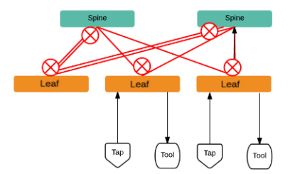
In a cluster, the number of leaf nodes is typically greater than the number of spine nodes. In the above figure, there are three leaf nodes and two spine nodes. The leaf nodes aggregate to a fewer number of spine nodes.
The spine nodes are generally GigaVUE TA Series nodes, such as GigaVUE-TA100, while the leaf nodes are GigaVUE HC Series nodes, such as GigaVUE-HC1, GigaVUE‑HC2, GigaVUE‑HC3, which places the traffic intelligence at the edge.
The figure shows TAPs or tools connecting to the leaf nodes, and the leaf nodes connecting to the spine nodes. Note that TAPs or tools do not connect to the spine nodes.
Instead of one leaf node connecting to one spine node with a single link, in this architecture there are multiple links from the leaf nodes to the spine nodes. The leaf nodes connect to the spine nodes through at least two paths. Some leaf nodes with higher capacity, such as GigaVUE-TA100, can have more paths, as shown by double red lines in the figure.
Traffic between ports on a leaf node will be local to that leaf node, but traffic between leaf nodes will go through the spine nodes.
The traffic from a source leaf node to a destination leaf node flows as follows:
| From a TAP, traffic flows to the source leaf node |
| From the source leaf node, traffic is load balanced to all spine nodes |
| From a spine node, traffic flows to the destination leaf node |
| From the destination leaf node, traffic flows to tool ports |
Resiliency is achieved when there are multiple paths from the network to the tools across GigaVUE nodes.


