Example 1: Unprotected Inline Bypass with an Inline Tool Group
Example 1 is a simple, unprotected inline bypass solution. In the example, aliases are used for inline network ports (iN1 and iN2), inline tool ports (iT1 and iT2), inline network (inNet), inline tool (inTool), and inline map (inMap).
On GigaVUE‑HC3, an unprotected inline bypass solution can be configured on the bypass combo module with the inline networks and inline tools on ports 1/1/x1..x16 or on ports c1..c4, or on any other module on the GigaVUE‑HC3 node.
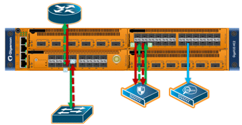
On GigaVUE‑HC2, an unprotected inline bypass solution can be configured with the inline networks and inline tools on ports 1/1/x1..x16 or on ports x17..x24, or on any other module on the GigaVUE‑HC2 node. Refer to 1 Logical Bypass Without Bypass Combo Module which shows a GigaVUE‑HC2.
|
1
|
Logical Bypass Without Bypass Combo Module |
On GigaVUE‑HC1, an unprotected inline bypass solution can be configured on the base module, with the inline networks and iniine tools on ports 1/1/x1..x12 and 1/1/g1..g4, or on the bypass combo module on ports x1..x4.
|
Task
|
Description
|
UI Steps
|
|
|
Configure inline network aliases, port type (inline-network), and administratively enable inline network ports.
|
|
1.
|
From the left navigation pane, go to System > Ports > Ports > All Ports. |
|
2.
|
Click Quick Port Editor. |
|
3.
|
Use Quick search to find the ports to configure. In this example, the ports are 3/1/x1 and 3/1/x2 |
|
4.
|
Set port 3/1/x1 to Type Inline-Network and select Enable. Enter iN1 for the port alias. |
|
5.
|
Set port 3/1/x2 to Type Inline-Network and select Enable. Enter iN2 for the port alias. |
|
6.
|
Make sure Enable is selected for Admin on the ports. |
|
|
|
Configure inline network.
|
|
1.
|
Select Inline Bypass > Inline Networks. |
|
3.
|
In the Alias field, type InNet. |
|
4.
|
For Port A, select iN1. |
|
5.
|
For Port B, select iN2. |
|
|
|
Configure inline tool ports, port type (inline-tool), and administratively enable inline tool ports.
|
|
1.
|
From the left navigation pane, go to System > Ports > Ports > All Ports. |
|
2.
|
Click Quick Port Editor. |
|
3.
|
Use Quick search to find the ports to configure. In this example, the ports are 3/1/x3 and 3/1/x4 |
|
4.
|
Set port 3/1/x4 to Type Inline-Tool and select Enable. Enter iT1 for the port alias. |
|
5.
|
Set port 3/1/x4 to Type Inline-Tool and select Enable. Enter iT2 for the port alias. |
|
6.
|
Make sure Enable is selected for Admin on the ports. |
|
|
|
Configure inline tool, and enable it. Also enable the default heartbeat profile.
|
|
1.
|
Select Inline Bypass > Inline Tools. |
|
3.
|
In the Alias field, type InTool. |
|
4.
|
For Port A, select iT1. |
|
5.
|
For Port B, select Ii2. |
a. Select Enabled
b. Select Enabled Heartbeat and set Profile to default.
|
|
|
Configure map passall, from inline network to inline tool.
|
|
3.
|
In the Alias field, type InMap. |
|
4.
|
Select Inline for Type and Pass All for Subtype. |
|
5.
|
For Source, select InNet |
|
6.
|
For Destination, select InTool. |
|
|
|
Configure the path of the traffic to inline tool.
|
|
1.
|
Select Inline ByPass > Inline Networks. |
|
2.
|
Select the Inline Network InNet and click Edit |
|
3.
|
Under Configuration, set the Traffic Path field to To Inline Tool. |
|


