Topology Visualization
The existing Topology page (Topology Classic page) in GigaVUE-FM displays the nodes and clusters managed by GigaVUE-FM in a single page. The nodes are placed randomly and the links connecting the nodes are scattered across the page. As a user, you are responsible for the accurate placement of the nodes, which is difficult in large deployment scenarios.
The new Topology page provides enhanced visualization of the nodes, thereby improving the usability of the page. The nodes are not shown in a single topology view, but are grouped based on pre-defined tags. The Topology page provides the following views:
- Tagged Layout Topology: The topology layout is based on predefined tags created by the user. Refer to Tagged Layout Topology section. The nodes can be grouped based on:
- Nature of deployment: Location of nodes such as region, state, city, datacenter.
- Placement: Aggregation nodes, leaf nodes, spine nodes.
- Smart Layout Topology: For smaller deployments, GigaVUE-FM creates predefined tags to group the nodes. Refer to the Smart Layout Topology section.
You can use the device level tagging to associate tags to the devices individually, as against the cluster-level tagging option. Refer to Device Level Tagging section for more details.
- The Topology Classic page is disabled to save system resources. Click Enable Classic Topology to enable.
- Once enabled, do not switch often between the Topology page and the Topology Classic page as this impacts the performance of GigaVUE-FM. Switch only if required.
- It is highly not recommended to switch between the existing and the pages in a scaled environment.
- On switching between the pages, it takes time for GigaVUE-FM to build the required infrastructure, and therefore it takes time for the pages to render.
Topology Visualization is supported in the following devices:
- GigaVUE-HC1, GigaVUE-HC2, GigaVUE-HC3
- GigaVUE TA Series devices
- Tool Devices discovered through CDP/LLDP and manual Tool Devices
Each of the individual nodes in a cluster can be associated with a tag key and a tag value. To assign a tag key to a device:
- On the left navigation pane, click on
 go to Physical > Nodes.
 - Click on Tags and enable the Device Level Tagging option.
- Select the required node(s). Click Tags and select Add. The Add Tags to Resources page appears.
- Select the required tag key and the tag value to which the nodes must be tagged.
- Click OK.
Note: Only aggregation tags can be configured to the devices.

The nodes in a cluster are now associated to tags which can be used for creating the required topology.
The Topology page displays smart layout topology for smaller deployments, in which the number of devices is less than or equal to fifty. GigaVUE-FM constructs the smart layout topology based on the port configuration. GigaVUE-FM applies the following types of tags to the devices:
- NETWORK DEVICES: External network devices are grouped under NETWORK DEVICES. By default, this is disabled. You must manually enable it to view the network nodes.
- GTAP NODES: Devices with internal tag value of GTAP_Nodes are grouped under GTAP NODES.
- TAP NODES: Devices with maximum number of network ports are grouped under TAP NODES.
- CORE NODES: Devices with maximum number of stack and circuit ports are grouped under CORE NODES.
- TOOL NODES: Devices with maximum number of tool ports are grouped under TOOL NODES.
- EXTERNAL TOOLS: External tools connected to the devices are grouped under EXTERNAL TOOLS.
-
Note: Use the Show Tools/Hide Tools option to display the external tools in the Topology page.
Note: GTAP NODES column is displayed only if GTAP is configured in GigaVUE-FM.
The devices that do not belong to either the TAP NODES or the TOOL NODES will be included in the CORE NODES category.
The edit option allows you to change the display names (default names) with the names of your choice for the following categories:
- TAP NODES
- CORE NODES
- TOOL NODES
You cannot edit the display name for the external tools.

- Click on a link or a device. The Connections Nodes and Analytics pane is displayed at the bottom. Refer to Smart Layout Topology section for details.
- You can drag and drop the devices across the columns to adjust the position of the nodes. The tags will get automatically updated.
- If the number of nodes exceeds 55: GigaVUE-FM prompts you with a message indicating that the smart layout topology is applicable only up to 75 nodes. You can either retain the existing layout or click Convert to Tagged Layout to create tagged layout topology. This option is available only for admin users with read-write access to the Infrastructure Management resource category.
- If 76th node is added to GigaVUE-FM: The newly added node will not be visible in the smart layout topology.
- If you switch to tagged layout topology: You cannot switch back to smart layout topology unless the device count becomes less than 50.
Tagged layout topology uses tags for grouping the nodes based on the following criteria:
- Hierarchical tags for grouping based on deployment: This allows you to drill down from a top-level hierarchical view to a lower-level detailed view.
- Placement tags for placement of nodes: This allows the you to see a detailed view of the devices from a left to right, source to tool view. Only single-valued tags can be used for this configuration.
When you first switch to tagged layout topology, if the devices have not been associated with tags, GigaVUE-FM prompts an error message to tag the devices from the physical nodes page.
Note:
- Only users with read-write access to the Infrastructure Management category can configure the required topology using tags. Refer to the 'Tags' section in the GigaVUE Administration Guide for detailed steps on how to create tags and how to associate the clusters/devices to tags.
- GigaVUE‑FM allows you to configure tags for the individual nodes in a cluster using the Device Level Tagging option. This allows tags to be associated at the device level and allows the devices to be grouped for visualizing the topology. Only aggregation tag type is allowed for tagging of the devices.
Using Hierarchy Tags you can group the nodes based on a specific hierarchical view. For example to create a hierarchy based on the location of the nodes, you must create the following tags ids and tag values:
| Hierarchy Level | Tag ID | Tag Values |
|---|---|---|
| I | Region | North, East, South, West |
| II | State | California, New York, Washington |
| III | City | San Francisco, Los Angels, Albany, |
| IV | Data Centers |
DC1, DC2 in San Francisco DC3 in Los Angels DC4 in Albany DC5 DC6 in Rochester DC7 DC8, DC9 in Seattle |
You are responsible for creating the appropriate tag keys and tag values and associate the nodes to the correct tag key and tag value to get the required hierarchical view of the tags. The tags can be either RBAC tags with hierarchical property set to True, or Aggregation tags.
Note: GigaVUE-FM does not validate the tag values assigned to the tag keys that are selected for hierarchical tag views. You are responsible for associating the correct tag keys and tag values to the nodes, so that the nodes are grouped appropriately.
Using placement tags, you can place the nodes in distinct columns. For example, to place the nodes based on the type of the node, the tag key must be 'Node Type' and the tag values can be one of the following:
- Tap_processing_node
- Tool_node
- Leaf_node
- Spine_node
Note: Only aggregation tags can be configured at the node level tags.
To configure tagged layout topologies based on hierarchical and placements view, refer to the following sections:
Keep in mind the following rules and notes while creating tagged layout topology:
- The tag keys and the tag values required for the hierarchical view and placement view must be created in advance.
- The devices must be associated to the appropriate tag keys and tag values for visualizing the topology.
- Gigamon Discovery Protocol (GDP) must be enabled on the nodes to visualize the links. For bulk configuration of GDP, refer to the "Port Discovery" page in the GigaVUE Administration Guide.
- The 'Device Level Node ID' allows you to associate tags to the devices, as against cluster-level tagging.
- You cannot drag and drop the devices across the hierarchical columns. That is, you cannot move the devices across the regions which is logically not possible from GigaVUE-FM GUI. However, you can drag and drop the devices with in the same row. That is, you can move the placements of the devices within the same location.
- On the left navigation pane, click on
 go to Physical > Topology.
 - Click Edit Configured Tags. This option is available only for admin users with read-write access to the Infrastructure Management resource category. The Topology Tag Configurator page appears.
- For Hierarchy Tags: Select the required Tag Keys that need to be added to the Selected Hierarchy Tags and click Add. Add the Tag Keys in the order based on which you want to drill down.
- For Placement Tags: Select the required single-valued tags that need to be added to the Placement tags and click Add. Add the Tag Values in the order based on which you want to view the nodes in a row.
- Click Save. The configuration is saved and the topology is displayed.
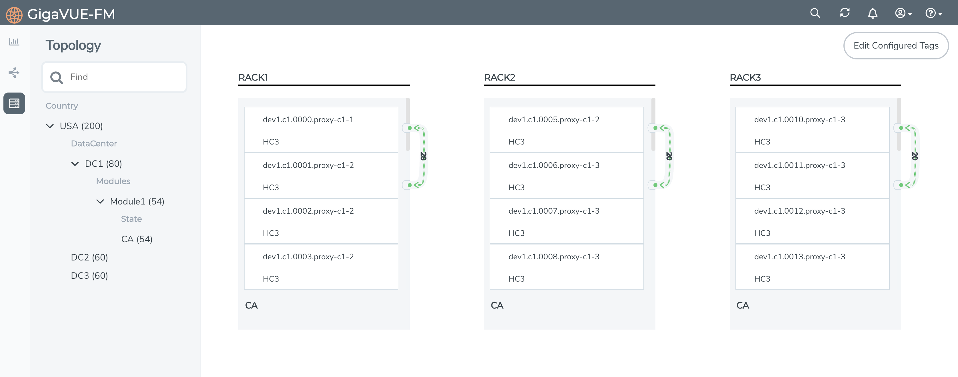
The Physical connections between the nodes across the groups are represented by a single consolidated line. Click on a specific node to view the physical connections of that node with other nodes.
Edit Topologies
To edit the topologies:
- Click Edit.
- Drag and drop the devices across the hierarchical columns.
- Click Save to save the changes.
The Edit Configured Tags option is also displayed under the edit option.
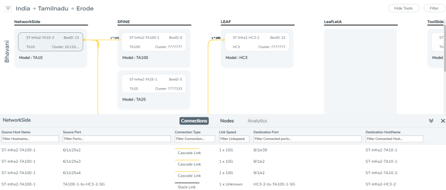
From the Topology page you can view the details of the devices and the connections associated with the devices for both smart layout and tagged layout topologies. Click on a link in the Topology page to view the following:
- Nodes: Displays details about the connected devices such as Cluster ID, Host name, Node IP, Model, Role, Box ID, and other such details.
- Connections: Displays details about the links connecting the Devices such as the host name, port or GigaStream Alias, Type of Connection, Link Speed and other details associated to the connection.
- Hover over the port id to view the health status of the port.
- Analytics: Displays the statistical details of the devices and the connections. Click on a specific device or a connection for which you need to view the details. The Analytics tab displays top 5 RX/TX packet drop, Data Rate (Octets) and utilization for a particular column, device or connection based on selection.
Note: For tagged layout topologies, the Analytics tab is enabled only for the tags at the last hierarchical level.
The Filter button allows you to filter the devices in the Topology page based on the following criteria:
- Model
- Cluster ID
- Host Name
- Tags
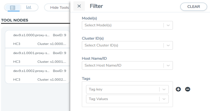
The filtered node will get highlighted.
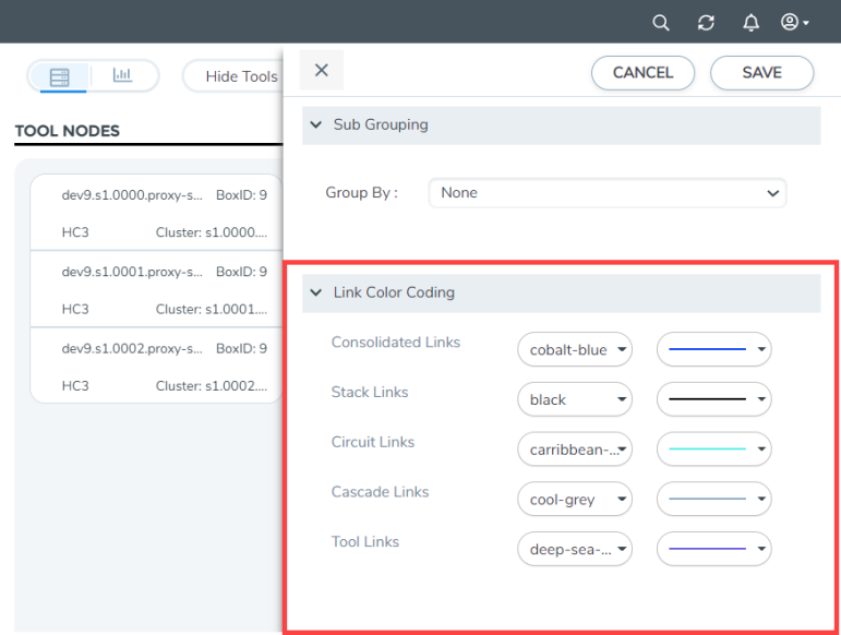
The colors and the format of the connections in the Topology page can be configured as follows:
- Click the ellipsis on the top right corner of the topology page.
- Use the Link Color Coding option to edit the colors and formats of the following types of connections:
- Consolidated Links
- Stack Links
- Circuit Links
- Cascade Links
- Tool Links
The changes are saved and will be applied for the connections when a new topology is created.
Note: Some of the colors available in the previous versions have been removed in software version 5.13.00. If you have used those colors in the previous versions, then on upgrading to software version 5.13.00, those colors will be replaced with the supported colors.
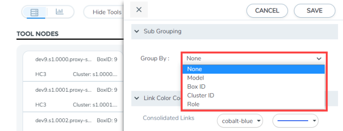
The Sub-Grouping option allows you to group the nodes in the Topology page:
- Click the ellipsis on the top right corner of the topology page.
- Use the Sub Grouping option to select the criteria based on which the nodes must be grouped:
- Model
- Cluster Id
- Box Id
- Role
The nodes can be grouped in both smart and tagged layouts topology.
The Topology page displays the links between the nodes and the external tools. The tools can be either manually added or discovered through CDP/LLDP by the tool port:
To add devices and links refer to the following section.
To add devices:
-
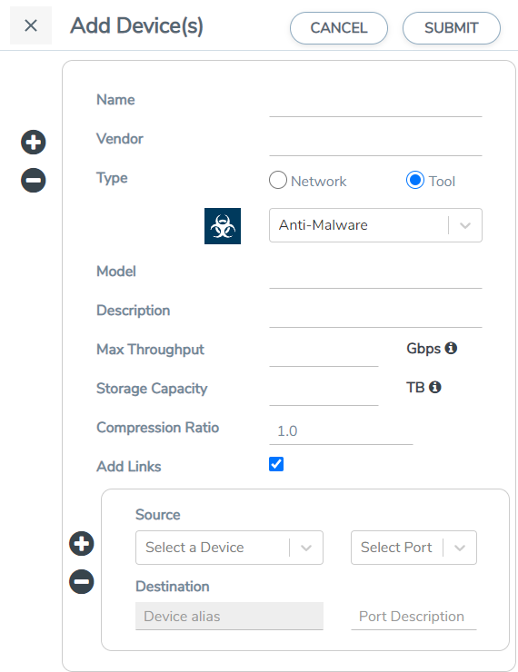
Select Add > Add Device(s)
 .
. -
You can add additional nodes by clicking the + button. To remove a node, click the - button.
| 1. | Enter the following information for the node: |
| Name—the name of the node. |
| Vendor—the node’s manufacturer. For Gigamon nodes, you cannot edit this field. |
| Model—the model number of the node. |
| Description—optional description or additional information about the node. |
| Max Throughput - the maximum throughput traffic currently being sent to this tool. |
| Storage Capacity - the total processing capacity dedicated to all Gigamon ports physically connect to the tool. |
Note: This field is not displayed when selecting a device type Network.
The information entered for the node displays when hovering over the icon on the topology. Also, the type selected determines the icon.
| 2. | Click in the Type field to select the type of device, either Network or Tool. Depending on your selection, the following icons are displayed: |
|
Type |
Icon |
|
| Network |
Router |
|
|
Switch |
|
|
|
Virtual Switch |
|
|
|
Load Balancer |
|
|
|
Firewall |
|
|
|
VOIP |
|
|
|
Cloud |
|
|
| Tool |
Analyzer |
|
|
Anti-Malware |
|
|
|
Customer Experience Management |
|
|
|
Application Performance Management |
|
|
|
Data Loss Prevention (DLP) |
|
|
|
Forensics |
|
|
|
Intrusion Detection System (IDS) |
|
|
|
Intrusion Prevention System (IPS) |
|
|
|
Next Generation Firewall (NGFW) |
|
|
|
SIEM |
|
|
|
Other |
|
| 3. | Click Submit. |
To add links:
To add a link or links between nodes:
-
Click Add Links.
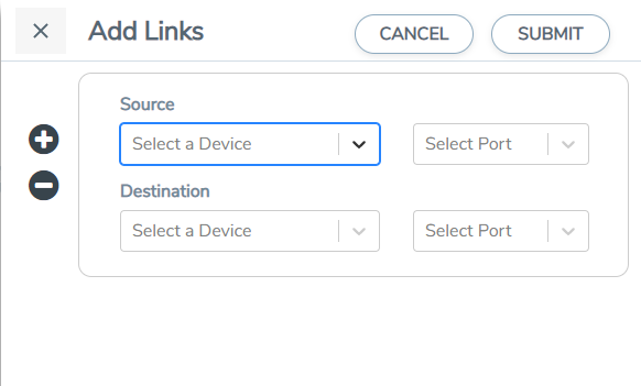
- Select the Source device and the required source port from the drop-down list.
- Select the Destination device and the required destination port from the drop-down list.
- Click Submit.
Note: You can also select GigaStream as source or destination for the topology and select the required ports.
Recently Viewed
The Recently Viewed pane allows you to view the list of recently viewed topologies. Use the Find in Recently Viewed to find the topologies that you last searched for.


