Add Applications to Monitoring Session
GigaVUE Cloud Suite with V Series 1 node supports the following GigaSMART applications:
You can optionally use these applications to optimize the traffic sent from your instances to the monitoring tools.
Sampling
Sampling lets you sample the packets randomly based on the configured sampling rate and then forwards the sampled packets to the monitoring tools.
To add a sampling application:
- Drag and drop Sample from APPLICATIONS to the graphical workspace.

- Click Sample and select Details.
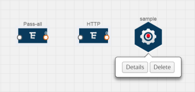
- In the Alias field, enter a name for the sample.
- For State, select the On check box to determine that the application is sampling packets randomly. Select the Off check box to determine that the application is not currently sampling the packets. The state can be changed at anytime whenever required.
- From the Sampling Type drop-down list, select the type of sampling:
- Random Simple — The first packet is selected randomly. The subsequent packets are also selected randomly based on the rate specified in the Sampling Rate field.For example, if the first packet selected is 5 and the sampling rate is 1:10, after the 5th packet a random 10 packets are selected for sampling.
- Random Systematic —The first packet is selected randomly. Then, every nth packet is selected, where n is the value specified in the Sampling Rate field.For example, if the first packet selected is 5 and the sampling rate is 1:10, then every 10th packet is selected for sampling: 15, 25, 35, and so on.
- In the Sampling Rate field, enter the ratio of packets to be selected. The default ratio is 1:1.
- Click Save.
Slicing
Packet slicing lets you truncate packets after a specified header and slice length, preserving the portion of the packet required for monitoring purposes.
To add a slicing application:
- Drag and drop Slice from APPLICATIONS to the graphical workspace.

- Click the Slice application and select Details.
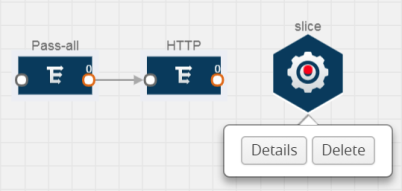
- In the Alias field, enter a name for the slice.
- For State, select On or Off check box to enable or disable slicing. The state can be changed at a later time whenever required.
- In the Slice Length field, specify the length of the packet that must be sliced.
- From the Protocol drop-down list, specify an optional parameter for slicing the specified length of the protocol. The options are as follows:
- None
- IPv4
- IPv6
- UDP
- TCP
- Click Save.
Masking
Masking lets you overwrite specific packet fields with a specified pattern so that sensitive information is protected during network analysis.
To add a masking application:
- Drag and drop Mask from APPLICATIONS to the graphical workspace.

- Click the Mask application and select Details.
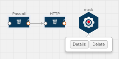
- In the Alias field, enter a name for the mask.
- For State, select On or Off check box to enable or disable masking. The state can be changed at anytime whenever required.
- In the Mask offset field, enter the offset from which the application should start masking data following the pattern specified in the Pattern field.The value can be specified in terms of either a static offset, that is, from the start of the packet or a relative offset, that is, from a particular protocol layer as specified in the Protocol field.
- In the Mask length field, enter the length of the packet that must be masked.
- In the Mask pattern field, enter the pattern for masking the packet. The value of the pattern is from 0 to 255.
- From the Protocol drop-down list, specifies an optional parameter for masking packets on the data coming from the selected protocol.
- Click Save.
NetFlow
NetFlow collects IP network traffic on all interfaces where NetFlow monitoring is enabled. It gathers information about the traffic flows and exports the NetFlow records, which includes data and templates, to at least one NetFlow collector. The application that serves as a NetFlow collector receives the NetFlow data sent from exporters, processes the information, and provides data visualization and security analytics.
The following are the key benefits of NetFlow application:
- Compresses network information into a single flow record.
- Facilitates up to 99% reduction in data transferred.
- Accelerates the migration of mission-critical workloads to your cloud environment.
- Provides summarized information on traffic source and destination, congestion, and class of service.
- Identifies and classifies DDOS attacks, viruses, and worms in real-time.
- Secures network against internal and external threats.
- Identifies top consumers and analyzes their statistics.
- Reduces the cost of security monitoring.
- Analyzes the network flows based on algorithms and behavior rather than signature matching.
- Analyzes east-west traffic between flows within and across VPCs.
The NetFlow application contains key elements that specify what to match in the flow, such as all packets with the same source and destination port, or the packets that come in on a particular interface. For information about Match/Key fields, refer to Match/Key Fields. A NetFlow record is the output generated by NetFlow. A flow record contains non-key elements that specify what information to collect for the flow, such as when the flow started or the number of bytes in the flow. For information about Match/Key fields, refer to Collect/Non-Key Fields.
The following figure shows an example of a NetFlow application created on a GigaVUE V Series node in the monitoring session.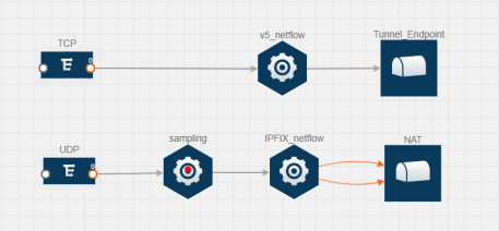
The NetFlow record generation is performed on GigaVUE V Series node running the NetFlow application. In Add Applications to Monitoring Session, incoming packets from G-vTAP Agents are sent to the GigaVUE V Series node. In the GigaVUE V Series node, one map sends the TCP packet to the version 5 NetFlow application. Another map sends the UDP packet to a sampling application. The map rules and applications such as slice, mask, and sample can only be applied prior to sending the data to NetFlow.
A NetFlow application examines the incoming packets and creates a single or multiple flows from the packet attributes. These flows are cached and exported based on the active and inactive cache timeout specified in the Netflow application configuration.
The flow records can be sent to a tunnel for full packet inspection or to a NAT device for flow inspection. NAT allows the NetFlow records to be directly transmitted to a collector without a tunnel. For more information about NAT, refer to Network Address Translation (NAT) .
The Netflow application exports the flows using the following export versions:
- version 5—The fields in the NetFlow record are fixed.
- version 9—The fields are configurable, thus a template is created. The template contains information on how the fields are organized and in what order. It is sent to the collector before the flow record, so the collector knows how to decode the flow record. The template is sent periodically based on the configuration.
- IPFIX—The extended version of version 9 supports variable length fields as well as enterprise-defined fields.
Match/Key Fields
NetFlow v9 and IPFIX records allow you to configure Match/Key elements.
The supported Match/Key elements are outlined in the following table:
|
Description |
Supported NetFlow Versions |
|
|
Data Link |
||
|
Destination MAC |
Configures the destination MAC address as a key field. |
v9 and IPFIX |
|
Egress Dest MAC |
Configures the post Source MAC address as a key field. |
IPFIX |
|
Ingress Dest MAC |
Configures the IEEE 802 destination MAC address as a key field. |
IPFIX |
|
Source MAC |
Configures the IEEE 802 source MAC address as a key field. |
v9 and IPFIX |
|
IPv4 |
||
|
ICMP Type Code |
Configures the type and code of the IPv4 ICMP message as a key field. |
v9 and IPFIX |
|
IPv4 Dest IP |
Configures the IPv4 destination address in the IP packet header as a key field. |
v9 and IPFIX |
|
IPv4 ICMP Code |
Configures the code of the IPv4 ICMP message as a key field. |
IPFIX |
|
IPv4 ICMP Type |
Configures the type and code of the IPv4 ICMP message as a key field. |
IPFIX |
|
IPv4 Options |
Configures the IPv4 options in the packets of the current flow as a key field. |
IPFIX |
|
IPv4 Src IP |
Configures the IPv6 source address in the IP packet header as a key field. |
v9 and IPFIX |
|
IPv4 Total Length |
Configures the total length of the IPv4 packet as a key field. |
IPFIX |
|
Network |
||
|
IP CoS |
Configures the IP Class Of Service (CoS) as a key field. |
v9 and IPFIX |
|
IP DSCP |
Configures the value of a Differentiated Services Code Point (DSCP) encoded in the Differentiated Services field as a key field. |
IPFIX |
|
IP Header Length |
Configures the length of the IP header as a key field. |
IPFIX |
|
IP Precedence |
Configures the value of the IP Precedence as a key field. |
IPFIX |
|
IP Protocol |
Configures the value of the protocol number in the IP packet header as a key field. |
v9 and IPFIX |
|
IP Total Length |
Configures the total length of the IP packet as a key field. |
IPFIX |
|
IP TTL |
For IPv4, configures the value of Time to Live (TTL) as a key field. For IPv6, configures the value of the Hop Limit field as a key field. |
IPFIX |
|
IP Version |
Configures the IP version field in the IP packet header as a key field. |
v9 and IPFIX |
|
IPv6 |
||
|
IPv6 Dest IP |
Configures the IPv6 destination address in the IP packet header as a key field. |
v9 and IPFIX |
|
IPv6 Flow Label |
Configures the value of the IPv6 flow label field in the IP packet header as a key field. |
v9 and IPFIX |
|
IPv6 ICMP Code |
Configures the code of the IPv6 ICMP message as a key field. |
IPFIX |
|
IPv6 ICMP Type |
Configures the type of the IPv6 ICMP message as a key field. |
IPFIX |
|
IPv6 ICMP Type Code |
Configures the type and code of the IPv6 ICMP message as a key field. |
IPFIX |
|
IPv6 Payload Length |
Configures the value of the payload length field in the IPv6 header as a key field. |
IPFIX |
|
IPv6 Src IP |
Configures the IPv6 source address in the IP packet header as a key field. |
v9 and IPFIX |
|
Transport |
||
|
L4 Dest Port |
Configures the destination port identifier in the transport header as a key field. |
v9 and IPFIX |
|
L4 Src Port |
Configures the source port identifier in the transport header as a key field. |
v9 and IPFIX |
|
TCP AcK Number |
Configures the acknowledgment number in the TCP header as a key field. |
IPFIX |
|
TCP Dest Port |
Configures the destination port identifier in the TCP header as a key field. |
IPFIX |
|
TCP Flags |
Configures the TCP control bits observed for the packets of this flow as a key field. |
v9 and IPFIX |
|
TCP Header Length |
Configures the length of the TCP header as a key field. |
IPFIX |
|
TCP Seq Number |
Configures the sequence number in the TCP header as a key field. |
IPFIX |
|
TCP Src Port |
Configures the source port identifier in the TCP header as a key field. |
IPFIX |
|
TCP Urgent |
Configures the urgent pointer in the TCP header as a key field. |
IPFIX |
|
TCP Window Size |
Configures the window field in the TCP header as a key field. |
IPFIX |
|
UDP Dest Port |
Configures the destination port identifier in the UDP header as a key field. |
IPFIX |
|
UDP Src Port |
Configures the source port identifier in the TCP header as a key field. |
IPFIX |
Collect/Non-Key Fields
NetFlow v9 and IPFIX records allow you to configure Collect/Non-Key elements.
The supported Collect/Non-Key elements are outlined in the following table:
|
Description |
Supported NetFlow Versions |
|
|
Counter |
||
|
Byte Count |
Configures the number of octets since the previous report in incoming packets for the current flow as a non-key field. |
v9 and IPFIX |
|
Packet Count |
Configures the number of incoming packets since the previous report for this flow as a non-key field. |
v9 and IPFIX |
|
Data Link |
||
|
Destination MAC |
Configures the destination MAC address as a non-key field. |
v9 and IPFIX |
|
Egress Des MAC |
Configures the post source MAC address as a non-key field. |
IPFIX |
|
Ingress Des MAC |
Configures the IEEE 802 destination MAC address as a non-key field. |
IPFIX |
|
Source MAC |
Configures the IEEE 802 source MAC address as a non-key field. |
v9 and IPFIX |
|
Timestamp |
||
|
Flow End Millisec |
Configures the absolute timestamp of the last packet of current flow in milliseconds as a non-key field. |
IPFIX |
|
Flow End Sec |
Configures the flow start SysUp time as a non-key field. |
IPFIX |
|
Flow End Time |
Configures the flow end SysUp time as a non-key field. |
v9 and IPFIX |
|
Flow Start Millisec |
Configures the value of the IP Precedence as a non-key field. |
IPFIX |
|
Flow Start Sec |
Configures the absolute timestamp of the first packet of this flow as a non-key field. |
IPFIX |
|
Flow Startup Time |
Configures the flow start SysUp time as a non-key field. |
v9 and IPFIX |
|
Flow |
||
|
Flow End Reason |
Configures the reason for Flow termination as a non-key field. |
IPFIX |
|
IPv4 |
||
|
ICMP Type Code |
Configures the type and code of the IPv4 ICMP message as a non-key field. |
v9 and IPFIX |
|
IPv4 Dest IP |
Configures the IPv4 destination address in the IP packet header as a non-key field. |
v9 and IPFIX |
|
IPv4 ICMP Code |
Configures the code of the IPv4 ICMP message as a non-key field. |
IPFIX |
|
IPv4 ICMP Type |
Configures the type of the IPv4 ICMP message as a non-key field. |
IPFIX |
|
IPv4 Options |
Configures the IPv4 options in the packets of the current flow as a non-key field. |
IPFIX |
|
IPv4 Src IP |
Configures the IPv6 source address in the IP packet header as a non-key field. |
v9 and IPFIX |
|
IPv4 Total Length |
Configures the total length of the IPv4 packet as a non-key field. |
IPFIX |
|
Network |
||
|
IP CoS |
Configures the IP Class Of Service (CoS) as a key field. |
v9 |
|
IP Protocol |
Configures the value of the protocol number in the IP packet header as a key field. |
v9 |
|
IP Version |
Configures the IP version field in the IP packet header as a key field. |
v9 |
|
IPv6 |
||
|
IPv6 Dest IP |
Configures the IPv6 destination address in the IP packet header as a key field. |
v9 |
|
IPv6 Flow Label |
Configures the value of the IPv6 flow label field in the IP packet header as a key field. |
v9 |
|
IPv6 Src IP |
Configures the IPv6 source address in the IP packet header as a key field. |
v9 |
|
Transport |
||
|
L4 Dest Port |
Configures the destination port identifier in the transport header as a non-key field. |
v9 and IPFIX |
|
L4 Src Port |
Configures the source port identifier in the transport header as a non-key field. |
v9 and IPFIX |
|
TCP AcK Number |
Configures the acknowledgment number in the TCP header as a non-key field. |
IPFIX |
|
TCP Dest Port |
Configures the destination port identifier in the TCP header as a non-key field. |
IPFIX |
|
TCP Flags |
Configures the TCP control bits observed for the packets of this flow as a non-key field. |
v9 and IPFIX |
|
TCP Header Length |
Configures the length of the TCP header as a non-key field. |
IPFIX |
|
TCP Seq Number |
Configures the sequence number in the TCP header as a non-key field. |
IPFIX |
|
TCP Src Port |
Configures the source port identifier in the TCP header as a non-key field. |
IPFIX |
|
TCP Urgent |
Configures the urgent pointer in the TCP header as a non-key field. |
IPFIX |
|
TCP Window Size |
Configures the window field in the TCP header as a non-key field. |
IPFIX |
|
UDP Dest Port |
Configures the destination port identifier in the UDP header as a non-key field. |
IPFIX |
|
UDP Src Port |
Configures the source port identifier in the UDP header as a non-key field. |
IPFIX |
Add Version 5 NetFlow Application
To add a version 5 NetFlow application:
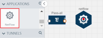
- Drag and drop NetFlow from APPLICATIONS to the graphical workspace.
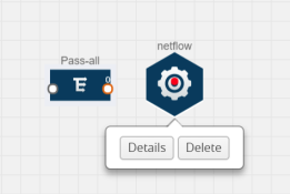
- Click the NetFlow application and select Details. A quick view is displayed for configuring the NetFlow application.
- In the Alias field, enter a name for the v5 NetFlow application.
- For State, select the On check box to determine that the application is currently running. Select the Off check box to determine that the application is currently not running. The state can be changed at anytime whenever required.
- From the NetFlow version drop-down list, select v5.
- In Active cache timeout, enter the number of seconds that an active flow record must remain in the cache before it is exported and removed. The default value is 1800 seconds.
- In Inactive cache timeout, enter the number of seconds an inactive flow record must remain in the cache before it times out. The default value is 15 seconds.
- Click Save.
For more examples demonstrating the NetFlow application configuration in the GigaVUE V Series nodes, refer to NetFlow Examples.
Add Version 9 and IPFIX NetFlow Application
To add a v9 and IPFIX NetFlow application:
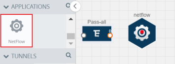
- Drag and drop NetFlow from APPLICATIONS to the graphical workspace.
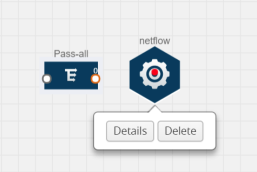
- Click the NetFlow application and select Details. A quick view is displayed for configuring the NetFlow application.
- In the Alias field, enter a name for the NetFlow application.
- For State, select the On check box to determine that the application is generating NetFlow records from the packets coming from the G-vTAP Agents. Select the Off check box to determine that the application is not currently generating NetFlow records. The state can be changed at anytime whenever required.
- From the NetFlow version drop-down list, select the version you want to use to generate the NetFlow records. The default version selected is v5.
- In the Source ID field, enter the observation domain to isolate the traffic. The NetFlow application uses source ID to segregate the records into categories. For example, you can assign source ID 1 for traffic coming over TCP. This results in generating a separate NetFlow record for TCP data. Similarly, you can assign Source ID 2 for traffic coming over UDP. This results in generating a separate NetFlow record for UDP data.
- From the Match fields drop-down list, select the parameters that identify what you want to collect from the incoming packets. The Match fields displayed in the drop-down list are based on the NetFlow version selected in step 5. Refer to Match/Key Fields.
- From the Collect fields drop-down list, select the parameters that identify what you want to collect from the NetFlow records. The Collect fields displayed in the drop-down list are based on the NetFlow version selected in step 5. Refer to Collect/Non-Key Fields.
- In Active cache timeout, enter the number of seconds that an active flow record must remain in the cache before it is exported and removed. The default value is 1800 seconds.
- In Inactive cache timeout, enter the number of seconds an inactive flow record must remain in the cache before it times out. The default value is 15 seconds.
- In Template refresh interval, enter the frequency at which the template must be sent to the tool. The default value is 1800 seconds.
- Click Save.
For some examples demonstrating the NetFlow application configuration in the GigaVUE V Series nodes, refer to NetFlow Examples.
Network Address Translation (NAT)
NAT allows the NetFlow records to be directly transmitted to a collector without a tunnel
The NetFlow records are exported to the collector over UDP protocol with the configurable source IP and destination IP.
Note: Only one NAT can be added per monitoring session.
Add NAT and Link NetFlow Application to NAT
To add a NAT device and create a link from a NetFlow application to a NAT device:
- Drag and drop NAT to the graphical workspace.

- Drag and drop a link from the NetFlow application to a NAT device. A Link quick view is displayed. It is a header transformation operation that lets you configure the IPv4 destination IP of the NetFlow collector.
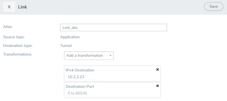
- Creating a Link from NetFlow to NAT
- In the Alias field, enter a name for the link.
- From the Transformations drop-down list, select any one of the header transformations:
- IPv4 Destination
- ToS
- Destination Port
Note: Only the above three header transformations are allowed on the link from the NetFlow application to a NAT device.
- In IPv4 Destination, enter the IP address of the NetFlow collector.
- (Optional) By default, the Destination Port is 2055. To change the destination port, enter a port number.
- Click Save. The transformed link is displayed in Orange.
- Repeat steps 7 to 10 to send additional NetFlow records to NAT.
NetFlow Examples
This section provides an example to demonstrate the NetFlow application configuration in the GigaVUE V Series nodes. Refer Example 1 below.
Example 1
In this example, a pass all map is created and the entire traffic from a VPC is sent to a tool for full packet inspection. At the same time, a NetFlow application is added to generate flow records for flow inspection.
- Create a monitoring session.
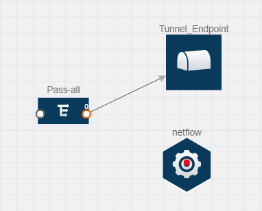
- In the monitoring session, create a Pass all map. A pass all map sends all the traffic received from the G-vTAP Agents to the tunnel endpoint or NAT.
- Drag and drop a tunnel from Tunnels. A tunnel encapsulates the flow records and then sends them to the tools for full packet inspection.
- Create a link from the Pass-all map to the tunnel endpoint. The traffic from the Pass-all map is forwarded to the tunnel endpoint that is connected to a tool.
- Drag and drop a v5 NetFlow application.
- Click the NetFlow application and select Details. The Application quick view is displayed. For steps to configure the v5 NetFlow application, refer to Add Version 5 NetFlow Application.
- Create a link from the Pass all map to the v5 NetFlow application.
- Drag and drop NAT to the graphical workspace.
- Create a link from the v5 NetFlow application to NAT. The link must be configured with the destination IP address of the NetFlow collector and the GigaVUE V Series node interface. For steps to configure the link, refer to Add Applications to Monitoring Session.
- Click on the link created from the v5 NetFlow application to NAT. The information about the NetFlow collector destination IP and port is displayed.


