Configuration Netflow Generation
The following are the step for setting up a typical NetFlow Generation configuration with H-VUE:
| Step 1: Configure a GigaSMART Group |
| Step 2: Configure the NetFlow Exporter |
| Step 3: Configure an IP Interface |
| Step 4: Configure the NetFlow Record |
| Step 5: Configure the NetFlow Monitor |
| Step 6: Add the NetFlow Monitor to GigaSMART Group |
| Step 7: Configure the GigaSMART Operation |
| Step 8: Configure Mapping Rules to Filter Packets |
Configure a GigaSMART Group using the following steps. you will use this GigaSMART Group in Step 6: Add the NetFlow Monitor to GigaSMART Group, where you assign a NetFlow Monitor to the group.
| 1. | From the device view, select GigaSMART > GigaSMART Groups. |
| 2. | Click New to create a new GigaSMART Group or select an existing GigaSMART Group and click Edit. |
| 3. | Enter an alias to help identify this GigaSMART group. For example, Netflow-gsgrp |
| 4. | Select an engine port (the e port references the GigaSMART line card or module) Your GigaSMART group should look similar to the example shown in the following figure. |

| 5. | Click Save. |
Notes:
| The GigaSMART Group can contain multiple GigaSMART engine ports. |
| Only one NetFlow Generation Monitor can be configured per GigaSMART Group. |
Configure one or more NetFlow Generation Exporters. There can be up to six NetFlow Generation Exporters for each NetFlow Generation Monitor.
To access GigaSMART within GigaVUE-FM, access a device that has been added to GigaVUE-FM from the GigaVUE-FM interface. GigaSMART appears in the navigation pane of the device view on supported devices. Refer to the Access GigaSMART from GigaVUE‑FM for details.
To configure the NetFlow Exporter, do the following:
| 1. | From the device view, select GigaSMART > NetFlow / IPFIX Generation > Exporters. |
| 2. | Click New. The NetFlow Exporters page appears. |
| 3. | On the NetFlow Exporter page, enter the information for the exporter. Table 1: NetFlow ExporterConfiguration Fields describes the fields. |
Note: The NetFlow version must be configured with the same version of the Exporter and the Record. If no version is specified, version 9 is the default.
| 4. | Under the Filters section, click Add a Rule to create a filter for the exporter. |
| 5. | Click Save. |
|
Field |
Description |
|
Alias |
The alias name for the NetFlow Exporter. |
|
Description |
An optional description of the NetFlow record. |
|
Format |
The format is either NetFlow or CEF. |
|
Version |
The version is either NetFlow-v9, NetFlow-v5, or IPFIX. |
|
Template Refresh Interval |
After each template-refresh-interval, the record template is sent to the collector. Also, the option template is sent. |
|
SNMP |
Enables SNMP packet support on IP interfaces associated with the NetFlow Exporter. |
|
Transport Protocol |
The UDP port of the collector. This value cannot be changed. |
|
IP Version |
IP Version of the destination IP. You can select IPv4 or IPv6. Default is set as v4. |
|
Destination IP |
The IP address of the NetFlow/IPFIX collector. Default is set as 0.0.0.0. |
|
Destination Port |
Port for the destination IP. Default is set as 2055. |
|
DSCP |
The DSCP priority of the packet. Default is set as 0. |
|
TTL |
The Time to Live of the packet. Default is set as 64. |
In this step, you identify the collector port and configure it as a tool port, where the NetFlow collector will be connected, and then configure an IP interface. The steps are as follows:
| 1. | Select the port to use and configure it as a tool port. |
| a. | Select Ports > Ports > All Ports. |
| b. | Click the Quick Port Editor button to open the Quick Port Editor. |
| c. | In the Quick Port Editor select the port to use for the IP interface, provide an alias to help identify the port (for example, NetFlow_Tunnel_Port), select Tool for the port type, and select Enable. |
| d. | Click OK. |
| 2. | Select Ports > IP Interfaces. |
| 3. | Click New. |
| 4. | On the IP Interface page, do the following: |
| a. | In the Alias and Description fields, enter a name and description for the IP interface. |
| b. | From the Port drop-down list, select the tool port that you configured in Step 1. |
| c. | Select the type of IP interface as either IPv4 or IPv6. |
| d. | Enter the IP Address, IP Mask, Gateway address, and MTU value. |
| e. | From the GigaSMART Group drop-down list, select the GigaSMART group you created in Step 1: Configure a GigaSMART Group. |
| f. | From the Exporters drop-down list, select the NetFlow exporter you created in Step 2: Configure the NetFlow Exporter. |
Configure a NetFlow Generation Record that has the following:
| match parameters that identify unique flows |
| collect parameters that identify fields you want to collect for the unique flows |
To access GigaSMART within GigaVUE-FM, access a device that has been added to GigaVUE-FM from the GigaVUE-FM interface. GigaSMART appears in the navigation pane of the device view on supported devices. Refer to the Access GigaSMART from GigaVUE‑FM for details.
To configure the NetFlow Record, do the following:
| 1. | From the device view, select GigaSMART > NetFlow / IPFIX Generation > Records. |
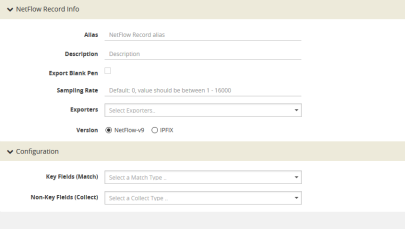
| 2. | Click New. The NetFlow record page shown in Figure 1 displays. |

| Figure 86 | NetFlow Record Page |
| 3. | On the NetFlow Record page, do the following: |
| a. | Specify the NetFlow Record information: |
| • | Enter an alias to help identify the record |
| • | Enter a Description (optional) |
| • | Enter the Sampling Rate that you want |
| • | Select the Exporter that you want from the Exporters menu |
| • | Select the Version |
The Version is either NetFlow-v9 or IPFIX. The NetFlow version must be configured with the same version of the Exporter and the Record. NetFlow-v9 is the default.
The Sampling Rate is multi-rate only, and is specified as 1 in N, where N is the packet count. The packet count can be a number from 1 to 16000. Refer to Configuration Netflow Generation. The Sampling Rate is disabled by default.
NetFlow-v9 and IPFIX let you configure Match/Key and Collect/Non-Key elements.
Make sure that you configure the NetFlow version prior to configuring the match and collect parameters because the subsequent parameters depend on the NetFlow version configured.
| b. | Specify the Configuration: |
Key Fields (Match) — the parameters that identify unique flows. The available Match/Key fields are based on the configured NetFlow version
Non-Key Fields (Collect) — the parameters that identify what you want to collect for the unique flows. The number of Collect/Non-Key elements in a record can be up to 32.
For details about the match and collect parameters, refer to Configuration Netflow Generation
Configure a NetFlow Generation Monitor and associate the NetFlow Generation Record to the specified NetFlow Generation Monitor by doing the following:
| 1. | From the device view, select GigaSMART > NetFlow / IPFIX Generation > Monitors. |
| 2. | Click New. The Monitors page displays. |
| 3. | On the Monitors page, do the following: |
| a. | Enter an Alias to identify the monitor. |
| b. | Enter a Description (optional). |
| c. | Configure the Cache parameters. Refer to Table 2: NetFlow Monitor Parameters. |
| d. | Configure the Sampling parameters. Refer to Table 2: NetFlow Monitor Parameters. |
| e. | Select the Record that you configured in Step 4: Configure the NetFlow Record. |
| 4. | Click Save. |
|
Parameter |
Description |
|||||||||
|
Cache Type |
Set as Normal. |
|||||||||
|
Cache Timeout Active |
Despite the flow being active, it is “flushed out” to the Exporter after this timeout, which is set in seconds. |
|||||||||
|
Cache Timeout Inactive |
Inactive flows are “flushed out” to the Exporter after this timeout, which is set in seconds. |
|||||||||
|
Cache Timeout Event |
Applies to the TCP flow. The flow is “flushed out” to the Exporter after detecting a FIN or RST. |
|||||||||
|
Mode |
Select the sampling mode that you want:
|
|||||||||
|
Single Sampling Rate |
Refer to Configuration Netflow Generation. |
Return to the GigaSMART Group configured in Step 1: Configure a GigaSMART Groupand set the NetFlow Monitor to the monitor created in Step 2: Configure the NetFlow Exporter.
| 1. | From the device view, select GigaSMART > GigaSMART Groups> GigaSMART Groups. |
| 2. | Select the GigaSMART Group configured inStep 1: Configure a GigaSMART Group, and then click Edit. |
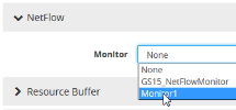
| 3. | Under GigaSMART Parameters, go to NetFlow. Click in the Monitor field and select the NetFlow monitor configured in Step 5: Configure the NetFlow Monitor as shown in the following figure. |

| 4. | Click Save. |
Define a GigaSMART operation to enable NetFlow Generation. If combining NetFlow with APF or De-duplication GSOPs, make sure that you select both operations when creating the GigaSMART Operation.
To access GigaSMART within GigaVUE-FM, access a device that has been added to GigaVUE-FM from the GigaVUE-FM interface. GigaSMART appears in the navigation pane of the device view on supported devices. Refer to the Access GigaSMART from GigaVUE‑FM for details.
To configure the GigaSMART Operation, do the following:
| 1. | From the device view, select GigaSMART > GigaSMART Operations (GSOP). |
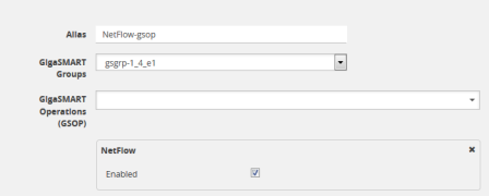
| 2. | Click New. The GigaSMART Operations (GSOP) page displays. (Refer to Figure 2.) |
| 3. | On the GigaSMART Operations page, do the following: |
| a. | In the Alias field, enter a alias to help identify this gsop. |
| b. | In the GigaSMART Groups field, select the gsop configured in Step 1: Configure a GigaSMART Group. |
cIn the GigaSMART Operations (GSOP) field, select NetFlow. The NetFlowGigaSMART Operation is enabled by default as shown in Figure 2.

| Figure 87 | GigaSMART Operation (GSOP) Page |
| 4. | Click Save. |
To add flow mapping rules to filter packets that are needed to run NetFlow, configure a map and associate the map to the IP interface with tool port.
For more detailed information about flow mapping, refer to About Flow Mapping® and Manage Maps.
Notes:
| For a single NetFlowGigaSMART Operation, make sure that you create a Regular By Rule map. When combining with APF or De-duplication, use First Level or Single Level map types. |
| Make sure that the other combining GigaSMART Operations are configured before creating maps using NetFlow. |
| When combining NetFlow with APF or De-duplication, create virtual ports to use with the second level maps. |
| The destination tool port must be the IP interface with tool port identified in Step 3: Configure an IP Interface |
For second level maps, you will need to create virtual ports. To create virtual ports, do the following:
| 1. | From the device view, select GigaSMART > Virtual Ports. |
| 2. | Click New. The Virtual Ports page displays. |
| 3. | Enter an alias in the Alias field to identify the virtual port. |
| 4. | In the GigaSMART Groups field, select the GigaSMART Group configured in Step 1: Configure a GigaSMART Group. |
| 5. | Click Save. |
To configure mapping rules to filter packets, do the following:
| 1. | Select Maps > Maps > Maps. |
| 2. | Click New to create a new map. |
| 3. | On the New Map page, do the following: |
| a. | Enter an alias in the Alias field and select the map Type and Subtype. |
| b. | Specify Source and Destination ports. |
| c. | In the GigaSMART Operations (GSOP) field, select the GigaSMART Operation configured in Step 7: Configure the GigaSMART Operation. |
| d. | Click Add a Rule to add the rules needed for the map. |
| 4. | Click Save. |


