Change Port Mode
Change port mode can be configured only on selected platforms. The port breakout modes are as follows:
| none—Specifies no port breakout mode. This is the default mode for all GigaVUE nodes. |
| 4x10G—Specifies the 4x10G port breakout mode. This mode provides a 4 x 10Gb breakout option for 100Gb/40Gb ports. The 4x10G mode only applies to GigaVUE-TA40, GigaVUE-TA100, GigaVUE-TA200, GigaVUE-TA100-CXP, the PRT-HD0-C06X24 line card on GigaVUE HD Series, and the PRT-HC3-C08Q08, PRT-HC3-C16, SMT-HC3-C05, and BPS-HC3-C25F2G modules on GigaVUE‑HC3. |
Note: Starting in software version 5.5, GigaVUE-TA40 supports 4x10G breakout at port level. Port breakout mode in GigaVUE-TA40 is configured as follows:
| 24 out of the 32 ports provide 4x10Gb breakout support. The first 12 ports and the last 12 ports provide support for breakout functionality with 96 sub-ports operating as 10Gb ports |
| Ports q1 to q12 and q21 to q32 support breakout functionality |
| Ports q13 to q20 do not support breakout functionality |
| Port are named as q1x1….q1x4, q2x1...q2x4 (similar to other hardware devices) to support the breakout functionality |
| 4x25G—Specifies the 4x25G port breakout mode. This mode provides a 4 x 25Gb breakout option for 100Gb QSFP28 SR ports. The 4x25G mode only applies to GigaVUE-TA200 and the PRT-HC3-C08Q08, PRT-HC3-C16, and SMT-HC3-C05 modules on GigaVUE‑HC3. |
| 2x40G—Specifies the 2x40G port breakout mode. This mode provides a 2 x 40Gb breakout option for 100Gb/40Gb ports. The 2x40G mode only applies to the PRT-HC3-C08Q08 module on GigaVUE‑HC3. |
For the BPS-HC3-C25F2G module on GigaVUE‑HC3, refer to the GigaVUE‑HC3 Hardware Installation Guide.
The 100Gb ports that support 4x10G mode can operate at 40Gb speed with QSFP+ SR or PLR4 transceivers. When a parent port is configured in 4x10G mode, it can be broken out into four 10Gb ports, called subports. The subports will all have the same speed (10Gb). Subports will have x1 to x4 appended to their port ID, for example, 1/1/c2x1.
The 100Gb ports that support 4x25G mode can be broken out into four times 25Gb ports, called subports. The subports will all have the same speed (25Gb). Subports will have x1 to x4 appended to their port ID, for example, 1/1/c2x1.
The 100Gb ports that support 2x40G mode can operate at 40Gb speed with QSFP+ SR and LR transceivers. When a parent port is configured in 2x40G mode, it can be broken out into two 40Gb ports, called subports. The subports will all have the same speed (40Gb). Subports will have q1 to q2 appended to their port ID, for example, 1/1/c1q1 and 1/1/c1q2.
In general, subports created from port breakout modes can function as network, tool, or hybrid ports, as well as GigaStream port members, but they cannot function as stack ports. However, starting in software version 5.3, 10Gb stacking is supported only on GigaVUE-TA100 and PRT-HC3-C08Q08 on GigaVUE‑HC3 when ports are broken out into 4x10G mode.
Note: On the PRT-HD0-C06X24 line card on GigaVUE HD Series, when 40Gb ports are broken out into 4 X 10Gb subports, no ports on that line card can be used as stack-links, not any other C port or any X port.
Each port can only have one mode.
The Chassis page has a Port Mode Editor available. The Port Mode Editor is used to set ports to breakout mode.To configure a port breakout mode, do the following:
| 1. | Click Change Port Mode. |
Note: The Change Port Mode button is only active on nodes that support it.
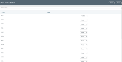
The Port Mode Editor page shown in Figure 1 Port Mode Editor displays.

| Figure 22 | Port Mode Editor |
| 2. | Select the Port Mode for the ports that you want configure: none, 4x10G, 4x25G, or 2x40G. For example, set port 36/1/c3 to 4x10G. |
Use the Quick search field to find a specific port. For example, entering 36/1/c3 in the Quick search field displays the ports with the IDs 36/1/c3, 36/1/c30, 36/1/c31, 36/1/c32.
| 3. | Click Save. |
The system returns you to the Chassis View page. For example on GigaVUE-TA100, the fanout ports are displayed in the chassis view as shown in Figure 2 Breakouts Displayed on a GigaVUE-TA100 Chassis. In Figure 2, the ports that are set to 4x10G show four additional ports.

| Figure 23 | Breakouts Displayed on a GigaVUE-TA100 Chassis |
After setting the port breakout mode, the ports will need break-out cables or breakout panel (PNL-M341 or PNL-M343). For breakout panel information, refer to the respective Hardware Installation Guide.


