Connecting -48V DC Power Supply Modules
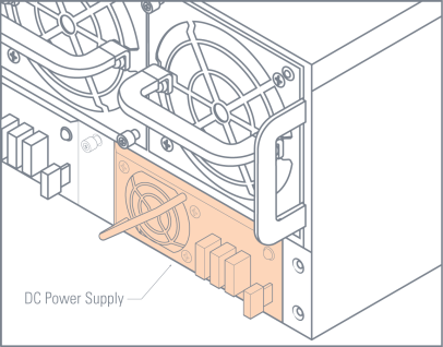
The GigaVUE‑HC3 is available with DC power supply modules. This section provides instructions for connecting a -48V DC power to the DC PSMs. Figure 1 shows a DC power supply module.

|
Figure 4
|
DC Power Supply Module |
To connect a -48V DC input to the screw terminal DC power supply module:
|
1.
|
Remove the safety cover from the power terminals. |
|
2.
|
Connect the power supply module ground terminal ( ) to earth ground. ) to earth ground. |
|
3.
|
Connect the positive and negative power cables to the screw terminals using a Phillips screwdriver. |
|
o
|
The top connector on the DC power supply module is the 0V connector. |
|
o
|
The bottom connector on the DC power supply module is the -48V connector. |
|
4.
|
Replace the safety cover over the power terminals. |
|
5.
|
Connect the neutral and negative power cables to the DC power source as follows: |
|
o
|
Connect the neutral wire to the 0V (RTN) connector on the DC power source. |
|
o
|
Connect the negative wire to the -48V connector on the DC power source. |
|
6.
|
Repeat Step 2 through Step 5 for the other PSMs in the GigaVUE‑HC3 chassis: |
|
o
|
GigaVUE‑HC3 – Four DC power supply modules |
Note: DC Power Electrical Safety Guidelines – For Permanently Connected Equipment, a readily accessible disconnect device shall be incorporated external to the equipment

 ) to earth ground.


