Node Topology
The Node Topology provides the same functionality as the Topology view displayed for all clusters nodes, and nodes discovered by GigaVUE‑FM or manually added. For details, refer to Overview of Topology. Node Topology displays the topology of individual clusters and standalone nodes and their immediate neighbors, whereas Topology displays all clusters nodes, and nodes discovered by GigaVUE‑FM or manually added. Nodes in a cluster are displayed inside a yellow container. Figure 1 is an example of a cluster with four nodes and a number of connected nodes.
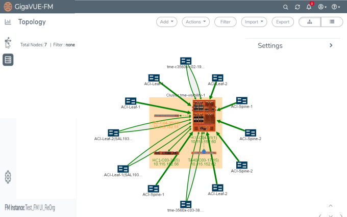
| Figure 35 | Physical Node Topology of a Cluster |
In Node Topology, only the immediate neighbors of the node is displayed in the topology. Figure 2 Node with Two Immediate Neighbors shows a topology where the node with the host name HC2-03-13 was selected. It has two immediate neighbors, so the topology shows the node and its two neighbor nodes.
.

| Figure 36 | Node with Two Immediate Neighbors |
However, if the node with the hostname HC2-C04-29 is selected, it has only one immediate neighbor HC2-C03-13, so the Node Topology shows only those two nodes.
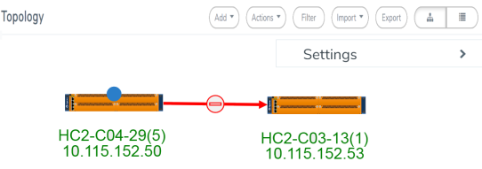
| Figure 37 | Node with One Immediate Neighbor |
The labels for each node provide basic information about the node: hostname, box ID, IP address. The color of the label indicates the node’s health. The node health colors are defined in Table 1: Node Health Status.
|
Node Health Status |
Meaning |
|
Green |
Node is healthy |
|
Amber |
Node is in a warning state |
|
Red |
Node id down |
|
Gray |
Node status is unknown or node is not reachable. |
The orientation of the nodes in the cluster container can be changed with the Align Cluster option in the context sensitive menu that appears upon right-clicking the cluster. You can also rearrange the chassis icons by clicking on the icon and dragging it to a new location. For more information about repositioning and aligning element in the topology, refer to Align Cluster.
Clicking on the graphic of a chassis shows the details about the chassis in a tool tip. In Figure 4, the details for a GigaVUE‑HC3 is displayed.

| Figure 38 | Details in Node Topology |
The color of the links between nodes and nodes connected to the cluster indicate the link status between the nodes and cluster. Stack links between nodes in the cluster appear as dashed lines. In Figure 1 Physical Node Topology of a Cluster, the stack links are between the GigaVUE‑HC3 node, GigaVUE-TA1, and GigaVUE-TA10. The thickness of the lines indicates the bandwidth of the link. The color of the links indicated its status. The colors are defined in Table 2: Link Status.
|
Link Status |
Meaning |
|
Green |
Link is up |
|
Amber |
Link is in a warning state |
|
Red |
Link is down |
|
Gray |
Link is in an unknown state. |
To display information about a link, click on the link to display a tool tip. The tool tip provides information about the link’s state, health state, link type (LLDP, CDP, or Gigamon Discovery), source leader in a bidirectional clock relationship (formerly master) and destination nodes, and source and destination ports
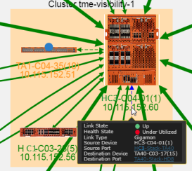
| Figure 39 | Link Information |
To display details about a link, right-click on a link and select More Details from the context menu. A Link Details quick view opens (refer Figure 6 Link Details). For more information about the Link Details quick view, refer to Link Details.

| Figure 40 | Link Details |
For details about GigaStream stack link details in leaf and spine cluster configuration, refer to GigaStream Stack Link Details.


