Microburst
A microburst is a very intense traffic transmitted in a short period of time. It is a situation in which a large amount of burst data is received in milliseconds, where the burst data rate is much higher than the egress port's bandwidth.
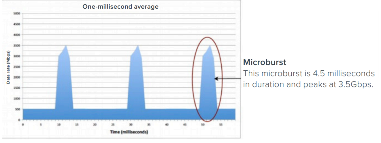
For example, two 100Gb ingress ports transmit traffic to a 10Gb egress port at an average rate of 1Gbps each. The aggregate bandwidth utilized will be 2Gbps (1Gbps x 2 network ports), which is well within the bandwidth of the 10Gb egress port. However, if there is a sudden spike in traffic from one of the ingress ports, that is, traffic is transmitted at a rate of 3.5Gbps in 4.5 milliseconds (as shown in the figure below), it is referred to as a microburst.

When the traffic is aggregated, packets are received at the egress port, usually from multiple ingress ports, in parallel rather than one after another. This results in queuing of packets. GigaVUE‑OS devices have some amount of buffer to queue these packets. Each port accesses this buffer dynamically, sharing this resource. This shared buffer is allocated to individual ports based on threshold values. If a port’s shared buffer usage reaches its threshold value, the subsequent packets that the port receives will be dropped by the device due to unavailability of buffer resources.
During microbursts, the port utilization will appear to be low, but packets will be dropped and the IfOutPktDrops counter will continue to increment.
Following factors impact the packets drop rate:
| Intensity of the microburst traffic. |
| Number of egress ports having microbursts at a given point in time. |
| Buffer absorption capability of the GigaVUE‑OS device. |
Best Practices to Improve Burst Tolerance
Keep in mind the following best practices when you design your topology to improve burst tolerance:
| If you have traffic flowing from a port with higher Gigabit to ports with lower Gigabit, that is, from a 40Gb port to four 10Gb ports, and bursty traffic is expected, one of the port can be internally modified into 4 x 25Gb and made as a hybrid port so the traffic flows from a 40Gb port to a 25Gb port, and then to a 10Gb port. However, you must create more than one map to implement this type of configuration. For more information about Hybrid ports, refer to Work with Hybrid Ports. |
| Increase the tool ports bandwidth by adding multiple tool ports to tool GigaStream so that traffic is distributed across multiple ports, and thereby minimizes the risk of microburst. Use the Advanced Hashing feature to select the hashing criteria. For more information, refer to Advanced Hashing. |
| Ensure that the egress ports are spread across different logical ports so that the load balancing and buffer utilization is effective. For example, you have a 40 Gb Gb (lower-case b) is defined as Gigabit and is a unit of bandwidth measured. It is the capacity to transfer information. egress port that is broken out in to four 10 Gb ports, ensure that two of the 10 Gb ports are in one logical group and the remaining two 10 Gb ports are in another logical group. For details about the logical grouping of ports, refer to Logical Grouping of Ports in GigaVUE‑HC3, GigaVUE-TA100, and GigaVUE-TA200. |
| Ensure that both ingress and egress ports through which traffic is flowing into and out of the network must be in the same logical group. Following table provides an example of the ingress and egress ports mapping in GigaVUE-TA100. For details about the logical grouping of ports, refer to Logical Grouping of Ports in GigaVUE‑HC3, GigaVUE-TA100, and GigaVUE-TA200 |
|
Egress Port |
Ingress Port |
Logical Group |
|---|---|---|
|
C1 |
C5 |
Group 0 |
|
C9 |
C14 |
Group 1 |
|
C18 |
C23 |
Group 2 |
|
C25 |
C32 |
Group 4 |
Logical Grouping of Ports in GigaVUE‑HC3, GigaVUE-TA100, and GigaVUE-TA200
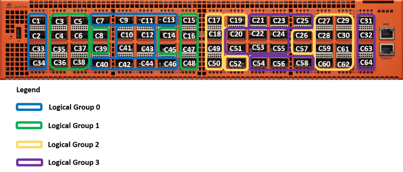
The ports in GigaVUE‑HC3, GigaVUE-TA100, and GigaVUE-TA200 are grouped in to four logical groups—Group 0, Group 1, Group 2, and Group 3. You must ensure that the ingress and egress ports are spread across these logical groups to improve burst tolerance.
| GigaVUE‑HC3—The ports in slot 1 are logically grouped into Group 0, ports in slot 2 into Group 1, ports in slot 3 into Group 2, and ports in slot 4 into Group 3. |
| GigaVUE-TA100—Following diagram illustrates the logical grouping of ports in GigaVUE-TA100: |

| GigaVUE-TA200—Following diagram illustrates the logical grouping in GigaVUE-TA200: |


