Standalone Node
Note: The following procedure is for a standalone GigaVUE‑HC2 node to upgrade the control card to HC2 CCv2. The software version on the HC2 CCv2 will be 4.6 or higher.
Before starting the procedure, backup the entire configuration on the node to a text file. This will later be used to reconfigure the HC2 CCv2.
(config) # configuration text generate active running upload <ftp | tftp | scp | sftp>://<upload URL>/<profilename.txt>
To upgrade a standalone GigaVUE‑HC2 node to HC2 CCv2:
- Log in to the serial console port on the node with the control card to be replaced and power it down gracefully with the reload halt command, confirming your decision when prompted, as follows:
|
Node_A [100: standby] (config) # reload halt Confirm reboot/halt? [no] yes Halting system... Node_A [100: standby] (config) # System shutdown initiated -- logging off. Gigamon GigaVUE H Series Chassis INIT:Stopping pm: [ OK ] Shutting down kernel logger: [ OK ] Shutting down system logger: [ OK ] Starting killall: Shutting down TFTP server: [ OK ] [ OK ] Sending all processes the TERM signal... Sending all processes the KILL signal... Remounting root filesystem in read-write mode: Saving random seed: Syncing hardware clock to system time Running vpart script: Unmounting file systems: Remounting root filesystem in read-only mode: Running vpart script: Halting system... sd 0:0:0:0: [sda] Stopping disk Power down. |
- Power down the standalone node by unplugging the power cable.
- The control card is located below the fan tray unit, which must be removed to access the control card. Remove the two screws on the fan tray unit as shown in the following figure, then remove the fan tray unit.

- Remove two lower screws as shown in the following figure.

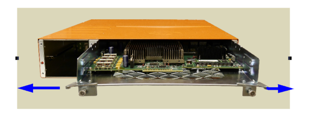
- Turn both latches outward as shown in the following figure to release the control card from the chassis.

- Remove the existing control card.
- Insert the new HC2 CCv2 control card.
- Turn both latches inward.
- Replace the two lower screws.
- Insert the fan tray unit and replace the two screws on the fan tray unit.
- Plug in the power cable.
- When the node powers up, log on to it over the console port.
- Switch to Configure mode.
| a. | Type en <Enter> to switch to Enable mode. |
| b. | Type config t <Enter> to switch to Configure mode. |
- Run the jump-start script with the following command if it does not appear automatically:
(config) # config jump-start
- Follow the prompts for the jump-start script.
- When the jump-start script has completed, run the following command to make sure the node has an IP address:
(config) # show interface eth0
- Log into the node and run the show card command. Refer to the following sample output. Verify that the control card in the cc1 slot has the correct type: HC2-Main-Board-v2. Initially, the other cards will be down and only the control card will be operationally up.
(config) # show cardBox ID: 1
Slot Config Oper Status HW Type Product Code Serial Num HW Rev
-----------------------------------------------------------------------------
cc1 yes up HC2-Main-Board-v2 132-00C2 1C20-0057 1.0-a0
1 yes down PRT-HC0-Q06 132-00BE 1BE0-01A2 B1-a3
2 yes down PRT-HC0-C02 132-00CR 1CR0-0034 3.0-a5
3 yes down SMT-HC0-X16 132-00BK 1BK0-001D 1.5-2
- Apply the previously saved configuration, using the following command:
(config) # configuration text fetch <http | https | ftp | tftp | scp | sftp>://<download URL>/<profilename.txt> apply fail-continue verbose
- Verify that the information on the GigaVUE‑HC2 with Control Card version 2 matches the previously saved configuration for chassis, cards, and traffic using the following CLI commands or others, depending on your configuration:
(config) # show version(config) # show chassis(config) # show cards(config) # show map(config) # show map stats all


