PRT-HC0-C02 Module
The PRT-HC0-C02 module provides two 100Gb QSFP28 ports, supporting 100Gb monitoring and aggregation.
The PRT-HC0-C02 is installed in the front module bays of the GigaVUE‑HC2.
Before installing the PRT-HC0-C02 module, the GigaVUE‑HC2 node must be running software version 4.6 or higher.
For details about the supported transceiver, cable type, fanout, inline ports, and clusters, refer to “GigaVUE-OS Compatibility and Interoperability Matrix”.
Note: The PRT-HC0-C02 can only be used on a GigaVUE‑HC2 node equipped with GigaVUE‑HC2 Control Card version 2 (HC2 CCv2). Refer to Figure 1 PRT-HC0-C02 Front Module.
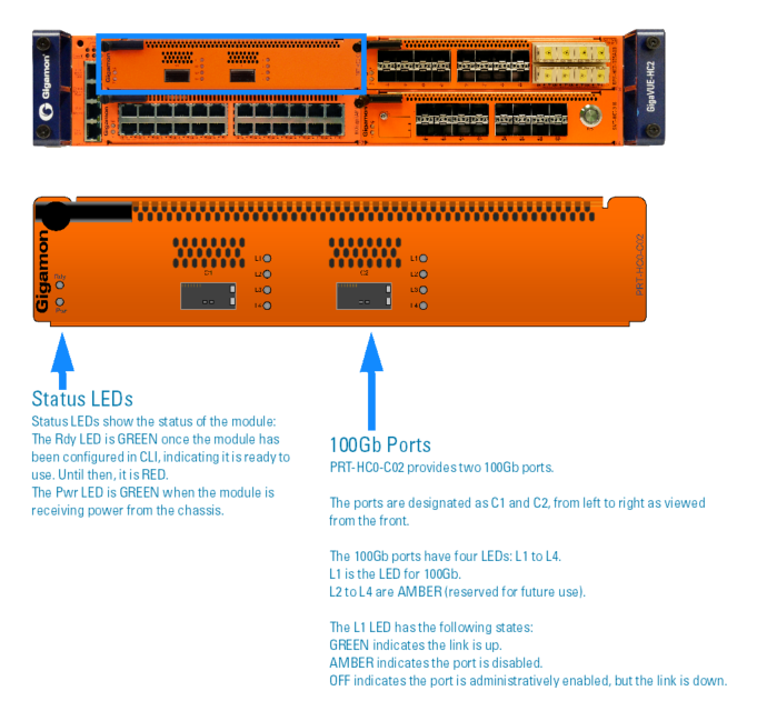
| Figure 6 | PRT-HC0-C02 Front Module |
Module Status LEDs
The module status LEDs are as follows:
| Rdy is the Ready LED. It has the following states: |
| • | RED indicates the system is booting up |
| • | GREEN indicates the system is ready |
| Pwr is the Power LED. It has the following state: |
| • | GREEN indicates the module is receiving power |
Port Status LEDs
The 100Gb port status LED, L1, has the following states:
| Off indicates the port is administratively enabled, but the link is operationally down |
| GREEN indicates the link is operationally up |
| AMBER indicates the port is disabled |
The 100Gb port status LEDs, L2 to L4, have the following state:
| AMBER indicates reserved for future use |
PRT-HC0-C02 Notes and Rules
Keep in mind the following notes and rules when using the PRT-HC0-C02 module:
|
PRT-HC0-C02 Notes |
|
|
Control Card Version 2 Required |
The PRT-HC0-C02 can only be used on a GigaVUE‑HC2 node equipped with GigaVUE‑HC2 Control Card version 2 (HC2 CCv2). |
|
Transceivers |
For details about the supported transceiver, cable type, and connectivity specifications, refer to “GigaVUE-OS Compatibility and Interoperability Matrix”. |
|
Maximum PRT-HC0-C02 Modules Per Chassis |
The maximum number of PRT-HC0-C02 modules per chassis is four, supporting up to eight 100Gb ports. Note: If all modules in the chassis are 100Gb, there are no 10Gb ports with which to connect tools. Refer also to 100G Chassis Mode for PRT-HC0-C02 and Module Placement of PRT-HC0-C02. |
|
Network, Tool, Hybrid, or Stack-Link Port |
The 100Gb ports on the PRT-HC0-C02 can be used as a network, tool, or hybrid ports. They cannot be used as stack-link ports. |
|
Inline Ports |
The 100Gb ports can be configured as inline network or inline tool ports, supporting 100Gb logical bypass. For details about the supported inline ports, refer to “GigaVUE-OS Compatibility and Interoperability Matrix”. |
|
Map Rules |
The PRT-HC0-C02 supports 16k (16383) map rules per module.The maximum number of rules per map is 4k (4096). |
100G Chassis Mode for PRT-HC0-C02
GigaVUE‑HC2 nodes equipped with Control Card version 2 (HC2 CCv2) AND 100Gb modules, PRT-HC0-CO2, require a chassis mode of 100G to be configured in software.
The platform PRT-HC0-CO2 has two modes default and 100G. The platform will be in default mode. To change the mode to 100G, first remove the existing configuration from the chassis, then configure the mode. For example:
(config) # no chassis box-id 1
(config) # chassis box-id 1 mode 100G| [left|right]
To switch to default mode, configure as follows:
(config) # no chassis box-id 1
(config) # chassis box-id 1 mode default
When the GigaVUE‑HC2 has a PRT-HC0-CO2 module installed and the mode is configured to 100G, the port count is limited to 42 ports on the columns of the node. Modules in bays 1 and 2 are the left column, and modules in bays 3 and 4 are the right column. Refer to Figure 1 Front View of the GigaVUE‑HC2 Chassis for a view of the front of the chassis. Also, refer to Module Placement of PRT-HC0-C02 for best practices when 100G mode is configured.
Starting in software version 4.7.01, you can optionally specify the 100G mode on either the left column or the right column of the node. For example:
(config) # chassis box-id 1 mode 100G left
When the left column is configured for 100G mode, install the PRT-HC0-CO2 module in the bays in the left column. The left column is subject to the 42 port limitation. The right column will not be limited to 42 ports, but you will not be able to install the PRT-HC0-CO2 module in the bays in the right column.
Conversely, when the right column is configured for 100G mode, install the PRT-HC0-CO2 module in the bays in the right column. The right column is subject to the 42 port limitation. The left column will not be limited to 42 ports, but you will not be able to install the PRT-HC0-CO2 module in the bays in the left column.
Module Placement of PRT-HC0-C02
With 42 ports per column, the best practices for placement of PRT-HC0-CO2 modules are as follows:
| Place PRT-HC0-CO2 modules in bays 1 and 3 or bays 2 and 4. This uses 2 ports on each column, leaving 40 ports for the other module in the column. |
| Use only one 24-port module per column. The 24-port modules are: PRT-HC0-X24, Bypass Combo Modules (BPS-HC0-D25A4G, BPS-HC0-D25B4G, BPS-HC0-D35C4G), and TAP modules (TAP-HC0-D25AC0, TAP-HC0-D25BC0, TAP-HC0-D35CC0, TAP-HC0-G100C0). |
Refer to Figure 2 Module Placement of PRT-HC0-CO2, 100G Mode for examples of incorrect and correct module placement when 100G mode is configured.
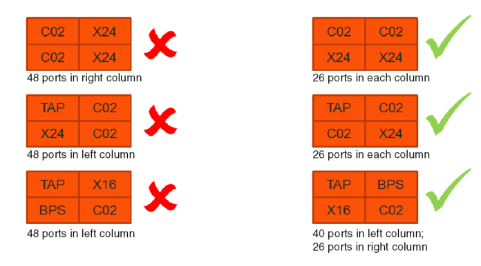
| Figure 7 | Module Placement of PRT-HC0-CO2, 100G Mode |
Refer to Figure 3 Module Placement of PRT-HC0-CO2, 100G Left Mode for an example of module placement when 100G left mode is configured.

| Figure 8 | Module Placement of PRT-HC0-CO2, 100G Left Mode |


