Connect and Configure G-TAP A Series 1 Nodes
This section describes how to assemble, connect, and configure the G-TAP A Series 1 devices. It includes the following major sections:
- Install G-TAP A Series 1 Battery
- G-TAP A Series 1 with the Rack Mount Tray
- Connect Power to G-TAP A Series 1
- How to Use Power Supply Tray
- Connect Console and Mgmt Ports
- Command Line Basics
- Configure Network/Monitor Ports on the G-TAP A-TX
- Configuring SNMP Trap Destinations
Install G-TAP A Series 1 Battery
The backup battery provides a failsafe in case all primary power sources (AC, DC, or PoE) are unavailable. Primary power sources constantly charge the backup battery until it is a 100% capacity and starts charging at 95% capacity, so it is ready to assume the power load in the event of a power failure on the primary sources.
The G-TAP A Series 1 is shipped with its backup battery uninstalled. If the battery is not installed, some packet loss might occur during a change in input power.
Note: You can install the battery GTA10 by Excell without disconnecting any existing power connections.
Use the following instructions to install the backup battery:
To Install the backup battery:
|
Steps |
Illustration |
|---|---|
|
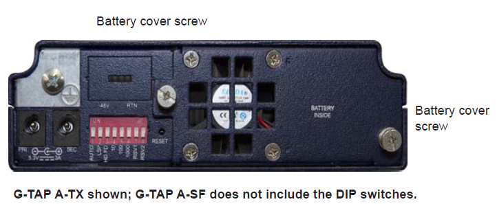
1. Locate the backup battery in your product shipment. 2. Place the tap upright on a flat surface. 3. Loosen the thumbscrews on the battery cover (shown at right) and remove it. 4. Disconnect the fan connector. |
|
|
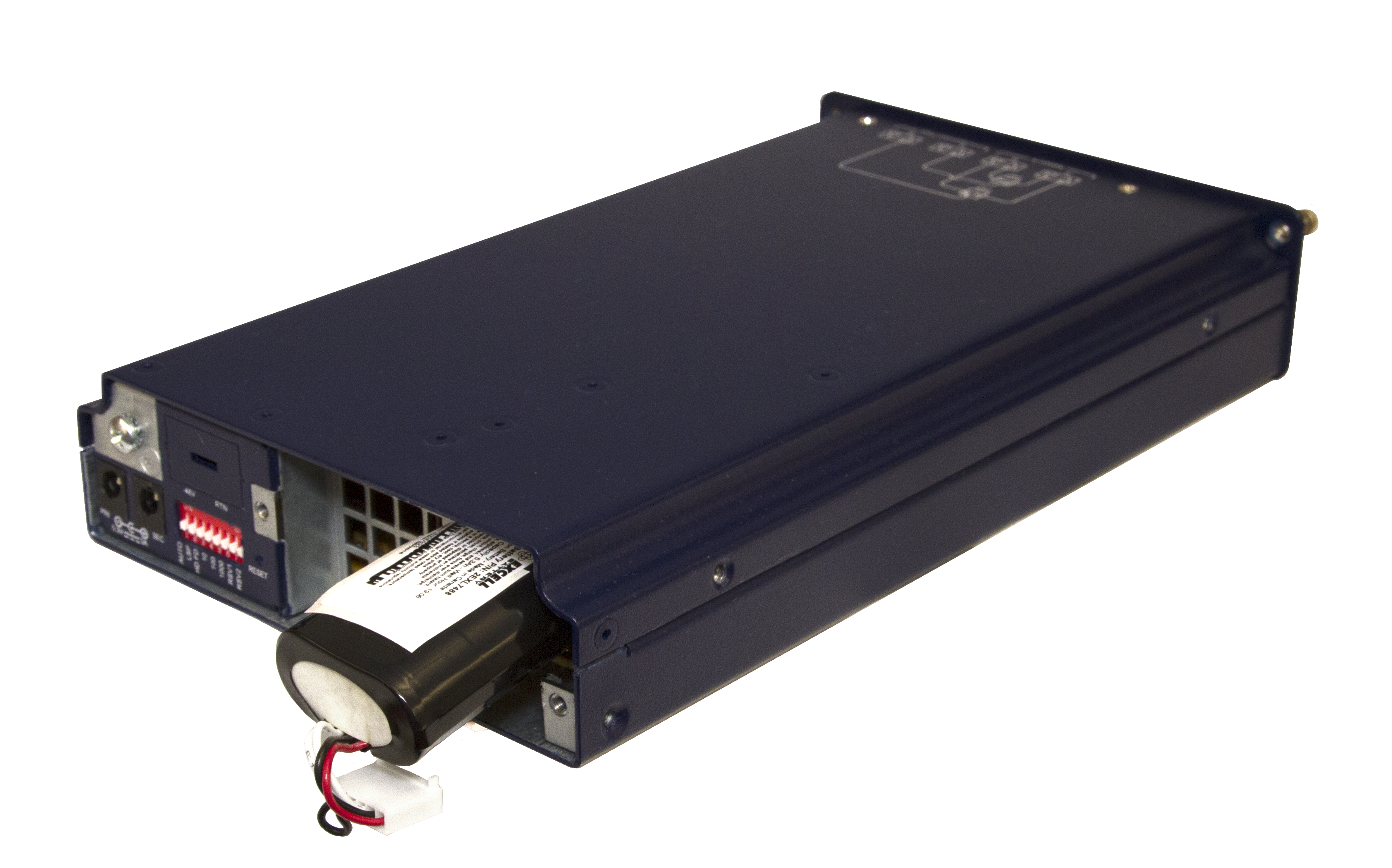
5. Orient the battery so that the battery connector is on the bottom. |
|
|
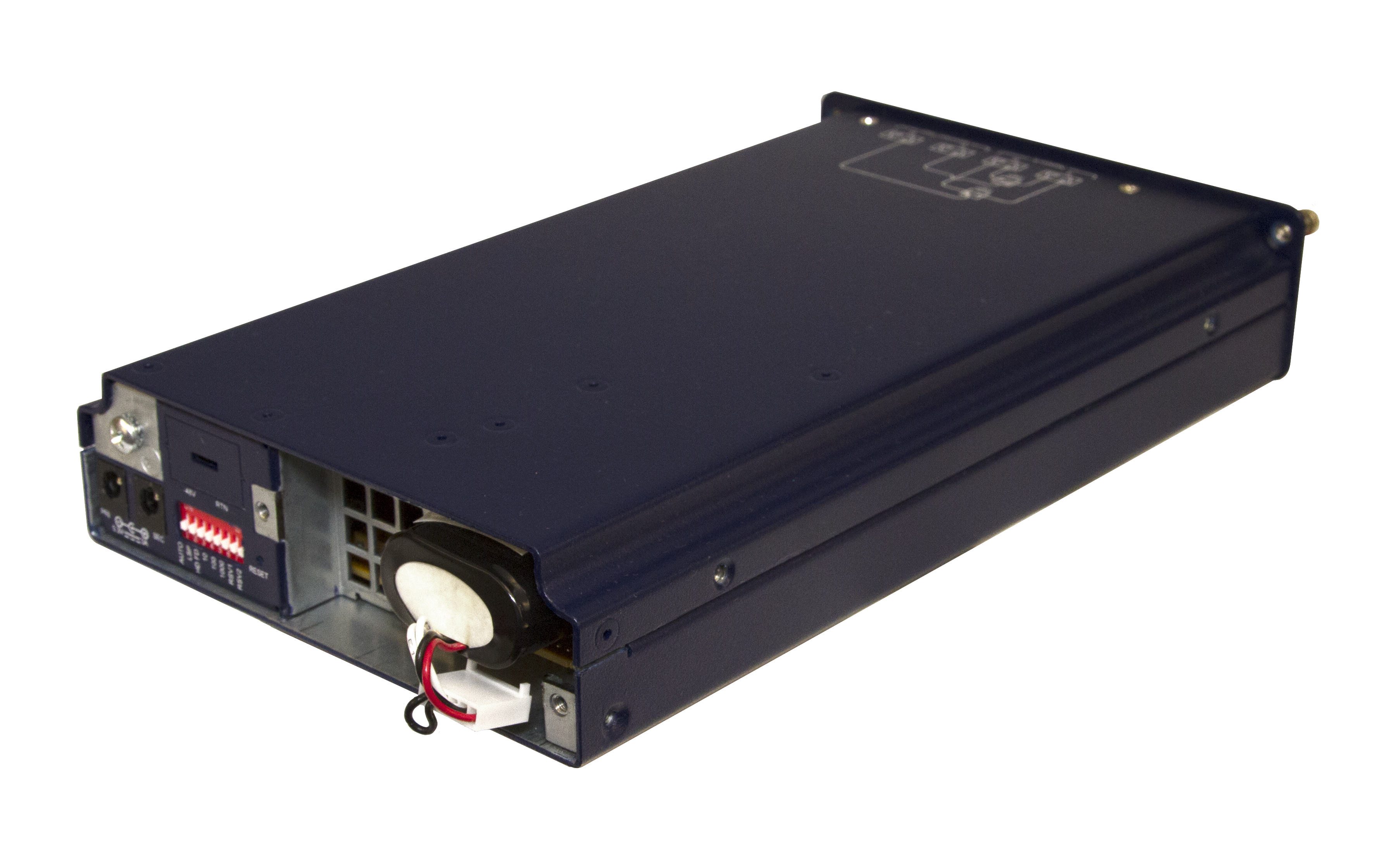
6. Slide the battery into the battery slot. 7. Reconnect the fan connector. Reinstall the battery cover, being careful not to touch the fan. The fan may be in operation during replacement. Refer to Fan Operation on page 17. 8. If a primary power source is not already connected, connect one now using the instructions in “Connecting Power to the G-TAP A Series” on page 4. |
|
CAUTION: ALWAYS USE BATTERIES PROVIDED BY GIGAMON. RISK OF EXPLOSION IF BATTERY IS REPLACED BY AN INCORRECT TYPE.
When a battery is installed to a G-TAP A Series 1 module for the first time, it is recommended that you do a manual battery exercise cycle to ensure that battery management is set to the normal condition. The battery exercise cycle is defined as follows:
- With battery installed in unit, charge the battery for 12 hours or until battery is full.
- Discharge the battery by unplugging the external power resource for 3 hours or until the battery is empty.
- Plug in the external power resource.
The G-TAP A Series 1 module is ready for use.
Note: When a battery is connected to the DW01+ for the first time, it may not enter the normal condition (discharge may not be enabled). In this case, short the CS and VSS pins or connect to a charger to restore to the normal condition.
Fan Operation
The G-TAP ATX fan operates if the main board temperature is equal to or greater than 50C (10%+/-) and/or the battery temperature is equal to or greater than 50C (10%+/-).
G-TAP A Series 1 with the Rack Mount Tray
G-TAP A Series 1 taps can be used either standalone or installed in the optional, three-across, 1U rack mount tray. Install taps in the rack mount tray as follows:
- Select an open bay from one of the three bays in the front of the rack mount tray and remove its protective slot cover.
- Gently slide the module into the target slot until the faceplate is flush with the chassis.
- Tighten the thumbscrews on the module faceplate.
- The rack mount tray installs in a standard 1U rack space using the provided hardware. You can install in two-post or four-post racks with a minimum width of 17.75”.
Connect Power to G-TAP A Series 1
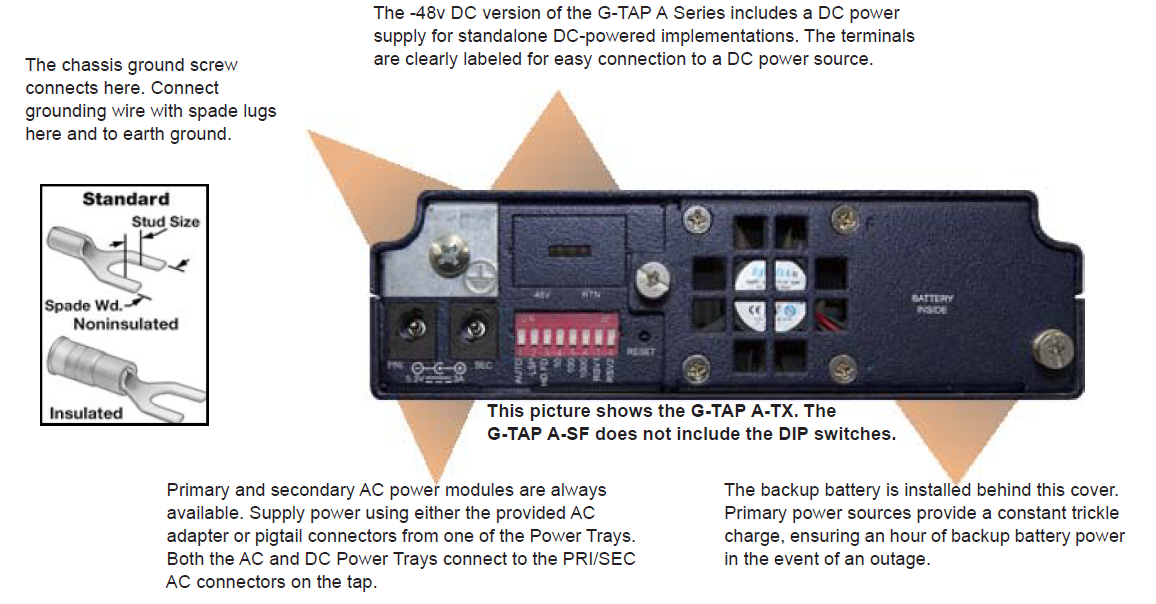
Supply power to the G-TAP A Series 1 using at least one of the primary power sources listed in Connect and Configure G-TAP A Series 1 Nodes. Connect and Configure G-TAP A Series 1 Nodes shows the location of the power connections. All primary power sources trickle charge the backup battery, ensuring a full charge in the event of power loss to primary sources.
Primary Power Sources
| Power Source | Connection Instructions |
|---|---|
|
AC |
|
|
DC |
|
|
PoE |
Connect the Mgmt port to a PSE device conforming to either the Type 1 (802.3af) or Type 2 (802.3at) Power over Ethernet implementations. Type 1 requires CAT3 or higher Ethernet cable; Type 2 requires CAT5 or higher. Note: PoE is used as a backup power source if either AC or DC power is connected. |
|
AC Power Tray |
|
|
DC Power Tray |
How to Use Power Supply Tray
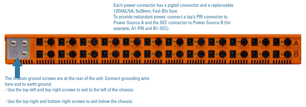
The optional PST-GTA0x Power Supply Tray can be used to power the G-TAP A Series 1 in a Restricted Access Location. A single 1U Power Supply Tray provides 24 power connections (A1-12 from Power Source A; B1-12 from Power Source B). This lets you supply redundant power to 12 separate taps (four fully-loaded RMT-GTA03 trays). Separate AC and DC models are available to match your data center needs. Connect and Configure G-TAP A Series 1 Nodes shows the front view of the power supply tray. Connect and Configure G-TAP A Series 1 Nodes shows the review of the power supply tray.
Power Supply Tray Connections
Make Power Supply Tray connections as follows:
- Rack-mount the unit. If you removed the power supply modules while rack-mounting the unit, reinstall them.
- Connect the chassis to earth ground. The correct ground screws are included with the unit (8-32x5/8”L, Phillips, Pan Head, Exterior SEM screw). See the diagram above for the location of the ground screws.
- Make sure the power supply modules are installed in the chassis and supply separate power sources to Power Sources A and B in the Power Supply Tray. Each Power Source has two inputs for a total of four in the tray.
- Connect ground wires to the DC power supplies.
- Connect the positive and negative power cables to the DC power supply screw terminals using a Phillips screwdriver. The top connector on the DC power supply is the 0V connector; the bottom connector on the DC power supply is the -48V return connector
- Connect the neutral wire to the 0V (RTN) connector on the DC power source.
- Connect the negative wire to the -48v connector on the DC power source.
- Once connected, the power tray and G-TAP A are considered PERMANENTLY CONNECTED EQUIPMENT. For safety compliance, you must:
- Incorporate a readily accessible disconnect device external to the DC power supply, such a as double pole switch or a circuit breaker.
- Have an overcurrent protective device. This is provided by the DC power supply, which contains a 10A fuse.
- Connect the provided male-to-male pigtail cables from the A1-A12 and B1-B12 connectors at the rear of the unit to the PRI/SEC connectors on individual taps. Twist the cables to lock them.
- For redundant power, connect a tap’s PRI connector to Power Source A and the SEC connector to Power Source B (for example, a single G-TAP A Series 1 could use A1-PRI and B1 - SEC for redundant power).
DC UNITS:For each DC power supply:
Power Supply Tray Specifications
The power specifications for the PST-GTA0x power supply tray are as follows:
|
Specification |
PST-GTA01 (AC) |
PST-GTA02 (DC) |
|---|---|---|
|
Input |
100V-240V AC, 4-2A, 47-63HZ |
-40V to -72 VDC, 10-5 A |
|
Nominal Input Current |
3 A @ 110V AC |
6.4 A @ -48VDC |
|
Nominal Power Consumption |
337 W |
308 W |
|
Nominal BTU Output |
1149 BTU/hr |
1050 BTU/hr |
Connect Console and Mgmt Ports
G-TAP A Series 1 taps include both a serial Console port and a 10/100 Ethernet Mgmt port (Connect and Configure G-TAP A Series 1 Nodes).
To connect the Console and Mgmt ports:
- Connect the RJ45 end of the provided DB9-to-RJ45 serial cable to the Console port of the G-TAP.
- Connect the DB9 end of the cable to a COM port on a PC or terminal server.
- Use a standard Ethernet cable to connect the Mgmt port to a network with access to a destination station for SNMP traps.
Note: Autonegotiation is always enabled on the Mgmt port of the G-TAP A Series 1 node. To avoid duplex mismatches, make sure autonegotiation is also enabled on the network port to which you connect the Mgmt port.
Connect to G-TAP A Series 1 CLI
You perform the initial configuration of the G-TAP A Series 1 node over the Console port. Once you have used the Console port to configure the Mgmt port’s network properties and enabled Telnet, you can configure the tap remotely over the Mgmt port’s network connection. The same commands are available in the command-line interface regardless of whether you use the Console or Mgmt port.
Note: You must configure the Mgmt port to send SNMP traps and download application images. These features are not available over the Console port.
|
Type of Configuration Sessions |
Instructions |
|---|---|
|
Local connections with a serial connection to the Console port. |
|
|
Remote connections with a Telnet connection to the Mgmt port. |
Serial Connections to the Console Port
A serial connection to the console port is made through a terminal emulation program. Either PuTTY or Tera Term is recommended.
Use the following procedure to establish a configuration session with the G-TAP A Series 1 over the Console port.
To access the command-line interface over the Console port:
- Make the basic power and Console cable connections described in previous sections.
- Start the terminal emulator (either PuTTy or Tera Term.) Go to the serial connection settings in the terminal emulator.
- Select the COM port connected to the Console cable from. For example, COM1.
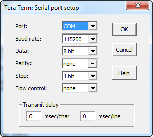
- Configure the port settings for the Console connection as shown in the following table and Configuring Serial Console Settings in Tera Term.
- Click OK and the terminal session begins.
- You may need to press Enter a few times before you see the login prompt. Enter the default password of root123. It is a good idea to use the passwd command to change the default after your first login.
|
Setting |
Value |
|---|---|
|
Bits per second |
115,200 |
|
Data bits |
8 |
|
Parity |
None |
|
Stop bits |
1 |
|
Flow control |
none |
|
Password |
root123 |
The G-Tap> prompt appears, giving you access to the built-in command-line interface. See Connect and Configure G-TAP A Series 1 Nodes for information on getting started with the CLI.
Telnet Connections to the Mgmt Port
Use the following procedures to establish a Telnet session with the G-TAP A Series 1 node over the Mgmt port.
As shown in Connect and Configure G-TAP A Series 1 Nodes, the Mgmt port is a standard RJ45 10/100 Ethernet port located in the upper left corner of the G-TAP A Series 1 node.
Configure Network Settings on the Mgmt Port
Before you can connect remotely to the Mgmt port, you must configure its IP settings over the Console port using the following procedure:
To configure the settings on the Mgmt port:
- Connect locally to the GigaVUE command-line interface (CLI) over the Console port using the instructions in Connect and Configure G-TAP A Series 1 Nodes.
- Use the config command to set network parameters for the Mgmt port. For example, the following command configures the port with a static IP address of 192.168.1.55:
config dhcp 0 ipaddr 192.168.1.55 subnetmask 255.255.255.0
These commands could also be issued separately:
config ipaddr 192.168.1.55 subnetmask 255.255.255.0config dhcp 0
Alternatively, you could use config dhcp 1 to obtain an IP address from a DHCP server automatically.
3. Use the config gateway command to set the default gateway. For example:
config gateway 192.168.1.1
4. Enable Telnet on the Mgmt port with the following command:
config telnet <0 | 1>
5. Reboot the G-TAP A Series with the reboot command to apply your changes, then ping the Mgmt port from another station to verify that the network parameters were applied as expected.
Connect to GigaVUE Using Telnet
When Telnet is enabled, you can use any compliant Telnet client to connect to the command-line interface remotely. For example, to connect using the Telnet client provided with Microsoft Windows:
- Open a command prompt window and type Telnet.
- Type open <Mgmt Port IP Address>.
- Supply the G-Tap Login Password (by default, root123).
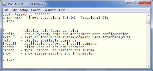
Connect and Configure G-TAP A Series 1 Nodes shows a sample Telnet connection to a G-TAP A Series node using the free TeraTerm client.
Command Line Basics
The G-TAP A Series command-line interface (CLI) provides a simple environment for configuring tap settings. Once you have logged in to the system, the CLI appears with the G-Tap > prompt. The basic G-TAP A Series commands are summarized in the following table:
|
Command |
|
Description |
|---|---|---|
|
? / help |
Shows help on available commands. |
|
|
BET |
RUN <now|0|1|..|90> SCHEDULE <disable|auto|random> |
Controls when to schedule the next BET. The RUN parameters specifies the number of days before the next test is run. If RUN is 0, the current BET is skipped and the next BET runs according to the SCHEDULE parameter. The SCHEDULE parameter controls the periodicity of the next BET, as follows:
|
|
brdtmp |
Displays the current ambient board and battery temperature. |
|
|
config |
[console_baud|baud <9600|14400|19200|38400|57600|115200>] |
Specifies the baud rate for the Console port . |
|
Specifies whether the G-TAP A Series node will obtain an IP address for its Mgmt port from a DHCP server (1) or use a static address (0). If you set dhcp to 1, do not supply values for ipaddr, subnetmask, or gateway. |
||
|
G-TAP A-TX Only Specifies whether to use the DIP switches at the rear of the unit for configuration of Network/Monitor port physical settings or the CLI.
Refer to Connect and Configure G-TAP A Series 1 Nodes
|
||
|
[ipaddr <addr> subnetmask <xxx.xxx.xxx.xxx>][gateway <xxx.xxx.xxx.xxxx>] |
Specifies the IP address, subnet mask, and default gateway for the Mgmt port. You only need to supply these values when dhcp is set to 0. |
|
|
[port-params <port_name> <operations> <args>] [admin <0 | 1>] [lsp <0 | 1>] [autoneg <0 | 1>] [duplex <half | full>] [speed <10 | 100 | 1000>] |
Configures network/monitor ports. You can configure different combinations of ports depending on the value specified for port_name, as follows:
The available arguments are as follows:
Refer to Connect and Configure G-TAP A Series 1 Nodes for details on how to use these arguments. |
|
|
config |
[remote_timeout <10 ~ 604800>] (seconds) |
Specifies how long the G-TAP A Series node waits before timing out an inactive Telnet session. Valid values range from 10 to 86400 seconds. The default is 300 seconds. |
|
[snmp_trap <args...>] [host <host_ip_addr>] [community <string>] [remove host <host_id>] |
Adds or deletes SNMP trap destinations . You can add up to four SNMP trap destinations, with each identified by a host_id from 0..3. All available trap events are enabled when at least one SNMP Trap destination is configured with config snmp_trap host. Refer to Connect and Configure G-TAP A Series 1 Nodes for details on working with SNMP features. |
|
|
[taptx <active|passive>] |
G-TAP A-TX Only Opens and closes the relays in the G-TAP A-TX:
|
|
|
[telnet <0 | 1>] |
Toggles the use of Telnet for the Mgmt port of the G-TAP A Series node. |
|
|
[time <hh:mm:ss>][date <mm-dd-yy>] |
Sets the time and date for the G-TAP A Series node. |
|
|
exit |
Logs out of the CLI. |
|
|
install |
Downloads a new application image from a TFTP server over the Mgmt port and installs it on the G-TAP A Series node. |
|
|
passwd |
Changes the password on the G-TAP A Series node. |
|
|
reboot |
Reboots the G-TAP A Series node. The CLI gives you the option of performing a Warm or Cold reboot: |
|
|
show |
Shows current settings on the G-TAP A Series node. You can use this command with any of the following arguments:
Note: The show diag command reports CRC errors differently on the G-TAP A-TX and G-TAP A-SF taps:
|
|
Command History
The G-TAP A Series 1 CLI remembers the last 10 commands you entered, allowing you scroll through previous commands with the up and down arrow keys.
Configure Network/Monitor Ports on the G-TAP A-TX
The G-TAP A-TX is shipped with autonegotiation enabled on the Network/Monitor ports and can be used out of the box by simply supplying power and connecting network cables.
You can also set explicit speed/duplex parameters for the Network/Monitor ports using either the DIP switches at the rear of the unit (the default) or the CLI. You specify which method to use with the config dip_sw override <0|1> command, as summarized below:
|
config dip_sw override 0 |
Use the DIP switches at the rear of the G-TAP A-TX to configure physical settings for Network/Monitor ports. This is the default setting for the G-TAP A-TX node. |
|---|---|
|
config dip_sw override 1 |
Use the config port-params arguments to configure physical settings for Network/Monitor ports. |
Configure Port Settings with the DIP Switches (G-TAP A-TX)
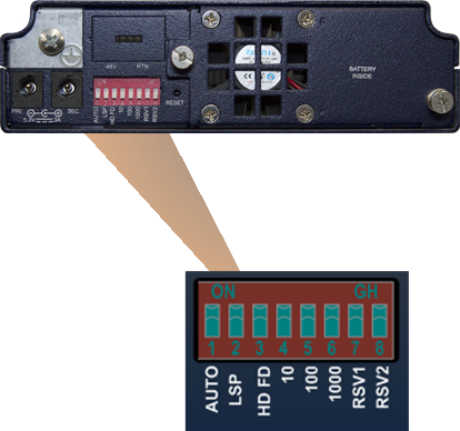
When config dip_sw override is set to 0 (the default), you use the DIP switches at the rear of the G-TAP A-TX (Connect and Configure G-TAP A Series 1 Nodes) to set explicit speed/duplex parameters for the Network/Monitor ports.
Keep in mind that any changes to the DIP switches are immediately applied to the Network/Monitor ports and will momentarily interrupt data flow while the ports are reset. Use show dip and show port-params to see current DIP switch settings and negotiated speed/duplex settings.
Note: Only the G-TAP A-TX includes DIP switches for port configuration. There are no user-configurable settings for ports on the G-TAP A-SF, other than the ability to administratively enable/disable ports.
Configuring Network/Monitor Ports with DIP Switches
|
Bit/Switch |
Description |
|
|---|---|---|
|
1 - AUTONEG |
Autonegotiation – When set to On, Bits 3-6 are ignored and the Network Ports autonegotiate speed and duplex settings with the connected link. The Monitor/Tool ports use the speed negotiated by the Network Ports. Note that autonegotiation is also enabled if all DIP switches are set to the Off position. |
|
|
2 - LSP |
Link State Propagation – When set to On, the G-TAP reacts to a link down event on one of the Network ports by forcing the other Network port down as well. |
|
|
3 - HD FD |
Duplex Mode – When set to On, duplex is forced to Full. |
Settings on DIP switches 3-6 apply to all Network/Monitor ports. If autonegotiation is disabled and more than one speed is selected (for example, switches 5 and 6 are both On), the tap uses the highest selected speed. |
|
4 - 10 |
10BASE-T – When set to On, link speed is forced to 10BASE-T (10Mbps). |
|
|
5 - 100 |
100BASE-TX – When set to On, link speed is forced to 100BASE-TX (100Mbps). |
|
|
6 - 1000 |
1000BASE-T – When set to On, link speed is forced to 1000BASE-T (1Gbps). |
|
|
7 - RSV1 |
Reserved |
|
|
8 - RSV2 |
||
Configure Port Settings in Software (G-TAP A-TX)
When config dip_sw override is set to 1, you can use the config port-params command to configure autonegotiation, link state propagation, duplex, and speed settings for the network/monitor ports.
The syntax for the config port-params command is as follows:
Usage: config port-params <port_name> <operations> <0|1>
port_name can be:
<all>, <network>, <toolA>, or <toolB>
operations can be:
[admin <0 | 1>] [lsp <0 | 1>] [autoneg <0 | 1>] [duplex <half | full>] [speed <10 | 100 | 1000>]
Arguments for config port-params
|
Argument |
Description |
|---|---|
|
lsp |
Link State Propagation – When enabled, the G-TAP A Series node reacts to a link down event on one of the Network ports by forcing the other Network port down as well. |
|
autoneg |
Autonegotiation – When enabled, the Network ports autonegotiate speed and duplex settings with the connected link. The Monitor/Tool ports use the speed negotiated by the Network Ports. |
|
duplex |
Duplex Mode – Specifies either half-duplex or full-duplex for the specified network/monitor ports. |
|
speed |
Speed – Sets the speed for the specified network/monitor ports to 10, 100, or 1000 Mbps. |
Examples:
|
Command |
Description |
|---|---|
|
config port-params all lsp 1 |
Enables link status propagation on all network/monitor ports. |
|
config port-params all speed 100 |
Sets the link speed to 100M on all network/monitor ports. |
Configuring SNMP Trap Destinations
G-TAP A Series nodes can send SNMP v2 traps to a maximum of four destinations based on a wide variety of events on the system, including system reboots, changes in power status (On/Off), battery level changes, or link status changes on any Network/Monitor port.
Configure SNMP settings by specifying a maximum of four destinations for traps and a community string with the config snmp_trap command:
config snmp_trap [host <host_ip_addr>] [community <string>] remove <host_id>
For example, the following command specifies a trap destination of 192.168.1.25 with a community string of gtap:
config snmp_trap host 192.1681.25 community gtap
The G-TAP A Series node automatically assigns a sequential Host ID to the new trap destination. You can use config snmp_trap with the remove argument to delete a host by specifying its Host ID. Use show snmp to see configured trap destinations along with their assigned IDs.
SNMP Trap Events
The G-TAP A Series supports the SNMP Trap events listed in the table below. You cannot enable traps individually—all traps are enabled when at least one SNMP Trap destination has been configured with config snmp_trap host.
The MIB for the G-TAP A Series is available for download from the company’s standard FTP site. Contact Customer Support for details. Once you have received a copy of the MIB, you can compile and load it into your SNMP Management software to view descriptions of the OIDs included in the traps.
The events available for trapping are slightly different between the G-TAP A-TX and the G-TAP A-SF. The following table calls out the events specific to one tap or the other.
|
Trap |
Description |
|---|---|
|
System Reboot |
Trap generated whenever the system reboots. |
|
Power Source Status Change |
Trap generated whenever the power source used by the tap changes (for example, from Primary AC to Battery). |
|
Power Event Status Change |
Trap generated whenever an AC, DC, or PoE power supply transitions from On to Off (or vice-versa). |
|
Battery Level % |
Traps generated at 25% increments as the available battery charge falls - 75%, 50%, and 25%. The last Battery Level % trap is the generated when the available battery charge falls to 15%. Then, the A Series node takes the following action:
|
|
Battery Presence |
The Battery Presence trap is generated in two cases:
|
|
Battery Exercise Started |
Trap generated when the Battery Exercise Test (BET) starts. |
|
Battery Exercise Ended |
Trap generated when the BET ends. |
|
Battery Exercise Missed |
Trap generated when the BET did not occur as scheduled. The BET occurs every 90 days. |
|
Hardware Problem During Battery Exercise |
Trap generated if a hardware problem is encountered during the BET. |
|
SOH |
Trap generated when the battery State of Health (SOH) is below the predefined threshold. |
|
Battery Temperature |
The Battery Temperature trap is generated in two cases:
|
|
Board Temperature |
The Board Temperature trap is generated in two cases:
|
|
G-TAP A-TX: Network/Tool Port Link Speed Info |
Trap generated whenever the speed of a Network/Tool port changes. |
|
G-TAP A-TX: Network/Tool Port Link Status Change |
Trap generated when the link status on any Network/Tool port transitions from Up to Down (or vice-versa). The trap indicates both the affected port and its speed. |
|
G-TAP A-SF:Network/Tool Port Signal Detect Change |
Trap generated whenever there is a change in the signal detected on any Network/Tool port (for example, light is detected on the ingress side of a port). |
