Connecting and Configuring G-TAP A Series 2
This section describes how to assemble, connect, and configure the
Connecting Power to the G-TAP A Series 2
The G-TAP A Series 2 uses AC/DC adapter, and the 1+1 redundant configuration is optional . To operate the node only a single power supply module is required . The steps to connect power adapters are as follows:
| 1. | Plug power adapter DC header into each power input modules at the rear of the G-TAP A Series 2. |
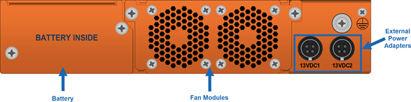
| 2. | Plug an approved C5 power cable into each of the power adapter. Plug the other end of the power cables into a power source that can supply adequate power. For optimal power protection, plug the power adapters into separate circuits. |
| 3. | When connecting to an external AC power source, ensure that a Surge Protective Device (SPD) is installed at the AC power inlet. |
| 4. | If you have not installed the battery pack , the power is turned on when the adapter is plugged in, and power is turned off when the adapter is removed. If you have installed the battery, G-TAP A Series 2 will remain always on until battery drains. |
Note: G-TAP A-SF21 battery operation time depends on the SFPs used.
To remove or replace a power adapter, refer to Remove or Replace the Power Adapter
Remove or Replace the Power Adapter
To remove or replace a power adapter follow below steps :
1. Disconnect the AC power cord to power down the adapter.
2. Disconnect adapter's DC header.
3. If new adapter is needed, replace the adapter and connect it back.
4. Repeat the first and second steps for other power adapter in the G-TAP A Series 2 chassis.
Refer Connecting and Configuring G-TAP A Series 2 to install the battery.
Installing the G-TAP A Series 2 Battery
The G-TAP A Series 2 is shipped with its backup battery uninstalled. The instructions below helps to install the backup battery. The backup battery provides a fail-safe in case all primary power sources (AC, DC ) are unavailable. Primary power sources constantly charge the backup battery so it’s ready to consume the power load in the event of a power failure on the primary sources. Battery charging from empty to full will take up to three hours
Note: You can install the battery without disconnecting any existing power connections.
Install the backup battery as follows:
- Locate the backup battery in your product shipment.
- Place the tap upright on a flat surface.
- Loosen the thumbscrews on the battery tray.
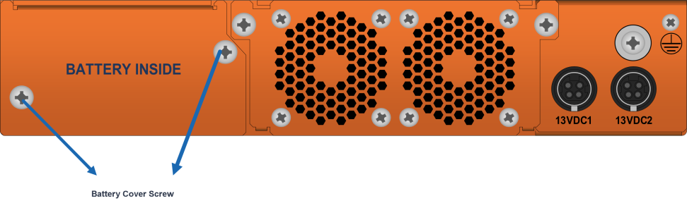
- Remove tape completely from golden finger of battery tray . After tape removal , handle the battery with care, to avoid golden finger's contact with any metal surface.
- Remove edge card protection tape from battery pack .
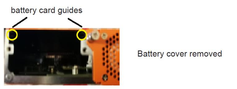
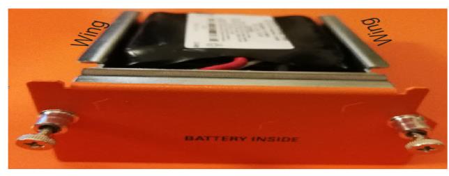
- Align battery pack's wings to the card guides on the chassis and fully insert battery pack in chassis .
- Orient the battery tray to insert it into the chassis
- Slide the battery tray into the battery slot. When the battery is fully installed, you should be able to read the text on the battery tray.
Power supply to the
CAUTION: ALWAYS USE BATTERIES PROVIDED BY Gigamon Inc. RISK OF EXPLOSION IF BATTERY IS REPLACED BY AN INCORRECT TYPE.
When a battery is installed to a G-TAP A Series 2 for the first time, it is recommended that you do a manual battery exercise cycle to ensure that battery management is set to the normal condition. The battery exercise cycle can be done by running BET command either in GigaVUE‑FM or in CLI.
Connecting Console and Management Ports
G-TAP A Series 2 TAPs include both a serial Console port and a 10/100/1000 Mgmt port .Follow the below instructions to connect the Console and Mgmt ports:
1. Connect the RJ45 end of the DB9-RJ45 serial cable, to the Console port.
2. Connect the DB9 end of the cable to a COM port on a PC or terminal server.
3. Use a standard Ethernet cable to connect the Mgmt port to a network with access to a destination station for SNMP traps.
Note: Auto-negotiation is always enabled on the
Note: G-TAP A-TX21-C is similar to G-TAP A-TX21 on all physical features and functionalities except that its management port and console port are disabled.
Connecting to the G-TAP A-TX21 CLI
The initial configuration of the G-TAP A-TX21 is performed over the Console port. Once you have used the Console port to configure the Mgmt port’s network properties , you can configure the TAP remotely over the Mgmt port’s network connection. The same commands are available in the command-line interface regardless of whether you use the Console or Mgmt port.
Note: You must configure the Mgmt port in order to send SNMP traps and download application images. These features are not available over the Console port
Access the Command-Line Interface over the Console Port
Use the console port on the left side of the base chassis to access the
| 1. | Make the basic power and console cable connections described in Connecting and Configuring G-TAP A series |
| 2. | Start a terminal application on the PC. Common terminal applications include TeraTerm, PuTTY, and Hyperterminal. |
| 3. | Select the COM port connected to the console cable attached to control module. For example, COM1. |
| 4. | Configure the port settings for the console connection as follows: |
| Bits per second – 115,200 |
| Data bits – 8 |
| Parity – None |
| Stop bits – 1 |
| Flow control – None |
Setting COM Port Properties for the Console Connection shows an example of how these settings are configured in Hyper-terminal.
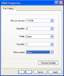
| Figure 3 | Setting COM Port Properties for the Console Connection |
| 5. | Start the terminal connection. You may need to press Enter a few times before you see the login: prompt. |
| 6. | Log in to the command-line interface with the following default user account and password: |
User:admin
Password:admin123A!
The configuration jump-start automatically starts and forces a password change.
The system administrator must change the password on the default admin account through the jump-start script. The default password (admin123A!) is no longer allowed. Refer to Run the Jump-Start Script for details.
A password must meet the following standards:
| include 8-30 characters |
| include at least one numeral |
| include at least one upper case letter |
| include at least one lower case letter |
| include at least one special character (for example, !, @, #, $, %, ^, &, or * – ASCII 0x21, 0x2F, 0x3A, 0x40, 0x5B, 0x5F, 0x7B, 0x7E) |
| Must not include the user name or parts of full-name. |
At the Admin password? prompt in the jump-start script, enter a new password that meets the standards, then confirm the password.
You will also configure some Admin and Monitor level users with the procedure described in Initial User Account Configuration.
Run the Jump-Start Script
Gigamon provides
| 1. | Switch to Configure mode. |
The G-TAP A-TX21 and G-TAP A-SF21 provides three command entry modes, each with increasingly powerful rights – Standard, Enable, and Configure. The jump-start script is only available in Configure mode:
| a. | Type en <Enter> to switch to Enable mode. |
The system prompt changes from [hostname]> to [hostname] #.
| b. | Type config t <Enter> to switch to Configure mode. |
The system prompt changes from [hostname] # to [hostname] (config) #.
| 2. | Run the jump-start script with the following command: |
(config) # config jump-start
| 3. | Follow the jump-start script’s prompts to configure each of the settings listed in the following table. |
Note: If you change your mind about a particular setting, you will have a chance to change it at the end of the script.
|
Hostname |
The hostname appears in the system prompt and is used to identify the chassis in SNMP traps. |
|||||||||
|
Management Port Network Settings |
Use either DHCP or specify a static IP address and netmask. If you do not use DHCP, you are prompted to configure the following additional options:
Supply the IP address of the default gateway for the node.
Supply the IP address of the DNS server for the node. A valid DNS server is required for successful use of TACACS+.
Supply the domain name for the node (for example, mycompany.com). |
|||||||||
|
Enable IPv6? |
You can enable the use of IPv6 for the management port. IPv6 is used in addition to IPv4 if you enable this option. If you enable the IPv6 you have the option of enabling IPv6 auto-configuration or specifying a static address. |
|||||||||
|
Admin Password |
The password for the admin account must be changed to a non-default password. |
| 4. | Review your settings. You can change a setting by specifying its listed line number and re-entering the setting. |
| 5. | When you are satisfied with your settings, exit the script as prompted. G-TAP A-TX21 and G-TAP A-SF21 automatically saves your settings. |
| 6. | Restart the node with the reload command. |
Initial User Account Configuration
Before you start mapping traffic, you must change the password for the admin account and add a few other accounts for use by different level users. (You may have already used the jump-start script to change the password for the admin account.)
Changing the admin Account Password
To change the password for the admin account using the username command, refer to the following:
(config) # username admin password <password>
Passwords must meet the following standards:
| Include 8-30 characters. |
| Include at least one numeral |
| Include at least one capital letter |
| Include at least one special character (for example, !, @, #, $, %, ^, &, or * – ASCII 0x21, 0x2F, 0x3A, 0x40, 0x5B, 0x5F, 0x7B, 0x7E). |
Enter a new password that meets the standards and confirm the password.
Setting Up Some Basic Accounts
Next, you will probably want to set a few user accounts with different access levels.
The TAP has a local account database that can optionally integrate with an LDAP, RADIUS, or TACACS+ server for authentication. Any account you want to authenticate using an external AAA server must have a matching account name in the local database.
Authentication, user levels, and roles are discussed in detail in the GigaVUE-OS CLI Reference Guide. For now, however, it is easiest to simply create a few basic user accounts with different privilege levels. In general, user privileges are as follows:
| Admin users have access to all command modes, including Standard, Enable, and Configure. They also have full permissions for all network, tool, and stack ports. |
| Operator users have access to all command modes, including Standard, Enable, and Configure. However, they only have access to the network and tool ports associated with their user group. |
New users are created with the operator role by default. You can add additional roles with the username <username> roles add <roles> command.
| Monitor users have access to the Standard and Enable command modes. They cannot configure packet distribution (or any other global G-TAP A-TX21 and G-TAP A-SF21 node options), but they can use the show command to review many of the settings in place on the node. |
The following username commands create a new admin user and a new operator user:
|
Command |
Comments |
|
(config) # username psandoval password Nine9.Eight8! (config) # username psandoval roles add admin |
Creates a new account named psandoval with a password, and grants it admin privileges. |
|
(config) # username bcrawford password Seven7.Six6! |
Creates a new account named bcrawford with a password. New users are automatically created with default operator level privileges, so there is no need to grant an additional role. |
Need to Change Any Settings?
If you need to change any of the settings you made in the jump-start script, you can either run the script again or change individual settings using the following commands in the Configure command mode:
| Use the hostname command to change the node’s hostname. |
| Use the interface eth0 command to reconfigure or fine-tune Mgmt port settings, including basic IP settings (DHCP or static address and subnet mask) and physical parameters (duplex, MTU, and speed). |
| Use the ip command to change the default gateway, DNS server, and domain name. |
| You can also use the username admin password <password> command to change the admin user’s password. Refer to Changing the admin Account Password. |
Refer to The Basic Commands for a quick summary of the available G-TAP A Series 2 commands.


