Cabling—Examples
This chapter provides examples of how to cable Test Access Points (TAPs), breakout panels, and devices. Refer to the following section for details:
| How to Cable a TAP to a Linecard |
| How to Connect a Breakout Panel to an Inline Bypass Module |
How to Cable a TAP to a Linecard
Before you cable a TAP to a linecard, you must understand how a TAP works. Also, you must determine whether you require a formal cabling plan.
Refer to the following sections for details:
| How a TAP Works |
| Create a Formal Cabling Plan |
| Cable a TAP to a Linecard |
How a TAP Works
A physical network TAP leverages hardware to copy traffic that travels between two devices—a network switch, a router, or an endpoint device to a secondary monitoring device, which is typically used for security or analytics. Most fiber TAPs are passive, that is, they do not require any power supplies, software, or configurations. Gigamon TAPs are the first step to visibility and offer perfect copies of all traffic at full bandwidth.
Network fiber cables can be considered as a pair of long strands of fiberglass used to pass light from one point to another. These cables are passive.
The transceivers, such as a Small Form-factor Pluggable (SFP), transmit and receive traffic. Transceivers have two primary components—an LED or a Laser to generate light signals and a light-sensitive receiver to capture the light signals. Since the LED or laser transmits the light signals, it is considered as Tx, while the light-sensitive receiver captures the light signals, it is considered as Rx. These two strands are separated at the place where the connections meet the transceiver. Every Tx leaving a device needs to be received by an Rx on the other end.
Most transceivers have arrows showing the physical direction of the traffic or light signal that is coming in (Rx) or going out (Tx) of the component. Refer to Figure 1.
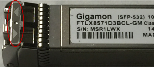
| Figure 1 | Transceiver With Incoming and Outgoing Arrows |
A passive fiber TAP does not contain any lasers or transceivers of its own. Instead, the TAP physically resides between the two devices that are being monitored as strands of fiber. Hardware splitter components within the TAP split a portion of the light that is transmitted from each direction, to a pair of separate monitor fibers, thus creating continuous copies of all traffic traversing the original links.
For each link that is tapped, a TAP will use three duplex ports, or connections. Figure 2 illustrates how a router and a switch is connected through a TAP.
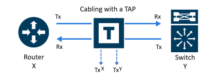
| Figure 2 | Cabling two devices with a TAP |
Let us name the port in the TAP that is connected to the Router as X and the port that is connected to the Switch as Y. Since these ports are duplex, each port will have a Tx and Rx subconnection. The third port connection on the TAP is different. It is reserved for the monitored traffic that has been copied. Therefore, both sides of this connection contain transmit traffic, TxX and TxY (Refer to Figure 3).
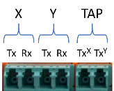
| Figure 3 | Tx and Rx Subconnection in TAP's Ports |
Create a Formal Cabling Plan
When cabling multiple TAPs for larger installations, you may lose track of cabling. It is recommended to adhere to a formal cabling plan. A cabling plan is a matrix that provides information about where every cable endpoint is connected. It includes detailed physical locations specifying the port that resides in a specific module, within a given slot, on a chassis that is on a specific RU within a given rack.
When you create a cabling plan, you must adhere to a nomenclature that allows you to understand the different slots in a TAP's chassis or module. Figure 4 illustrates the slot nomenclature for the G-TAP M Series TAP-M200 chassis that has 6 slots.

| Figure 4 | G-TAP M Series TAP-M200 chassis with Nomenclature for Slots |
Figure 5 illustrates the nomenclature for the G-TAP M Series TAP-M251 module.
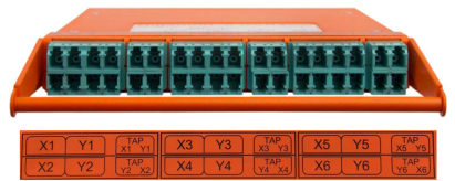
| Figure 5 | G-TAP M Series Module with Nomenclature for Six TAPs and LC Connectors |
Figure 6 illustrates the suggested categories to create a cabling plan.
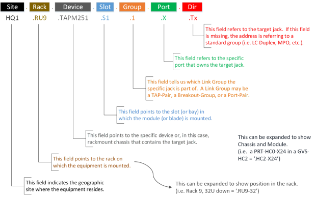
| Figure 6 | Suggested Categories for the Cabling Plan |
Figure 7 illustrates an example of a cabling plan to connect a monitoring port located in Slot 2 and Group 2 of the TAP-M251 to a network port, which is the second port in the PRT-HC0-X24 linecard that is located in Slot 2 of the GigaVUE‑HC2 device that receives traffic.

| Figure 7 | Example of a Cabling Plan |
Cable a TAP to a Linecard
For illustration purposes, this procedure uses the G-TAP M Series TAP-M251 module as an example. The TAP-M251 uses LC connections. As with most cabled devices, the top row is keyed at the top and the bottom row is keyed at the bottom to enable easy snap connections. The Tx and Rx ports are reversed on the bottom row. The TAP-M251 cabling setup is identical to that of the TAP-M271, TAP-M273, TAP-M453, and TAP-M473 modules. Although the TAP-M451, TAP-M471, and TAP-M471-SR10 use the larger MPO/MTP connections and tap fewer connections per module, the general cabling concepts still apply, except the output connections are not broken apart. The BiDi TAP module TAP-M506A works similarly. The patch panel modules PNL-M341 and PNL-M343 are not TAPs and are not covered here. For information regarding the patch panel cabling, general racking, or module insertion, refer to the G-TAP M Series Hardware Guide.
To cable a TAP-M251 to a Linecard:
| 1. | Connect a dual fiber cable from the X network device to the first dual LC connector on the TAP-M251. |
Note: LC connectors are keyed and will only fit in one direction. Ensure that the dual fiber cable matches the transceiver in use. Refer to the “Transceiver and Cable Matrix” tab in the GigaVUE-OS Compatibility and Interoperability Matrix for details.
| a. | If you are breaking an existing link: |
| Schedule a maintenance window because disconnecting cables causes an active link to go down. |
| Prior to unplugging cables, log into the device and jot down the port stats information to verify how much traffic is expected. |
| b. | Verify the port on device X is up, and traffic is flowing as expected. Ensure that device X is powered on. |
| c. | Verify light is passing to the TAP’s first LC monitor connection. |
Note: Never look at the laser light with the naked eye. Use the camera application on your mobile device to verify active connections are working. When the link is up on the device X, the first LC connector that monitors the link will show red as shown in Figure 8. The example shown here is using 10G MM.
Note: Some phone cameras include an infrared filter that eliminates the red, which prevents this from working. Check with your phone manufacturer to verify that you are using a phone camera with an option to capture infrared.
CAUTION: Do not look into a fiber to try to see the light. Fiber optic Ethernet light is not in the visible light spectrum. If you look into a fiber, you are likely causing eye damage.
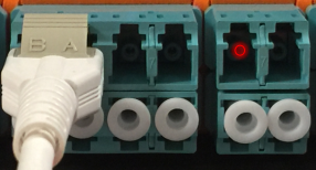
| Figure 8 | Red Light Passing to the First LC Connector (not visible to the human eye) |
| 2. | Connect a dual fiber cable from the Y network device to the second dual LC connector on the TAP. |
| a. | Verify the port on device Y is up, and the traffic is flowing as expected. Ensure that device Y is powered on. |
| b. | Verify light is passing to the TAP’s second LC monitor connection as shown in Figure 9. |
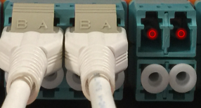
| Figure 9 | Red Light Passing to the First and Second LC Connectors (not visible to the human eye) |
| 3. | Connect cables to the TAP’s third pair of LC connections using cabling that can be separated into two LC connections. |
Note: These are monitoring ports with copies of the traffic moving between the X and Y devices. Both sides of this connection contain transmit traffic, TxX and TxY. For more information, refer to How a TAP Works.
| a. | When you connect the other ends of the single fiber cable to the GigaVUE node, make sure you only connect to the receiving half (Rx) of the network port. As specified earlier, transceivers have arrows indicating traffic direction. Only connect to the side of the transceiver with the arrow pointing in, to receive the traffic. Leave the transmitting half (Tx) of the port unconnected. Refer to Figure 10, Figure 11, and Figure 12. |
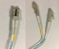
| Figure 10 | LC Connectors |
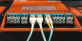
| Figure 11 | LC Connectors connected to TAP |
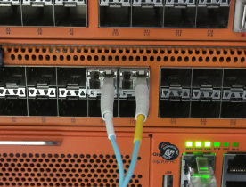
| Figure 12 | LC Connectors connected to GigaVUE Node |
| b. | Re-verify both X and Y devices have links up and are working properly. |
| c. | Verify the GigaVUE node has both incoming links up and is receiving appropriate traffic. |
How to Connect a Breakout Panel to an Inline Bypass Module
Figure 13 illustrates how to connect a PNL-M341 breakout panel to a BPS-HC3-C25F2G bypass combo module of GigaVUE‑HC3.
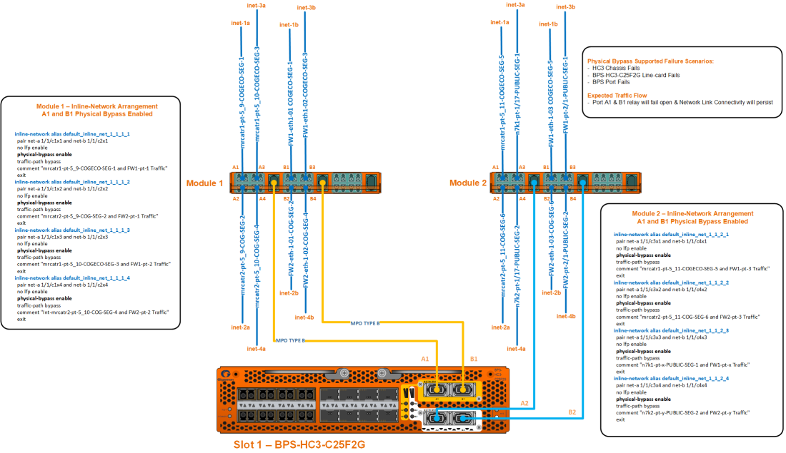
| Figure 13 | Connecting Breakout Panel to Inline Bypass Module |
The diagram depicts the A1 and B1 inline network mapping between 40Gb A1 and 40Gb B1 to 4x10Gb (A1 to A4 and B1 to B4) breakout ports. The inline network mapping for the breakout ports must be:
| A1 to B1 |
| A2 to B2 |
| A3 to B3 |
| A4 to B4 |
The diagram also outlines the various failure scenarios that physical bypass supports and the expected traffic flow.


