Configure GigaSMART Operation for Layer 2 GRE
To access GigaSMART within GigaVUE‑FM, access a device that has been added to GigaVUE‑FM from the GigaVUE‑FM interface. GigaSMART appears in the navigation pane of the device view on supported devices. Refer to Access GigaSMART from GigaVUE‑FM for details.
To configure the L2GRE encapsulation/decapsulation types and options, use the GigaSMART Operations (GSOP) page:
| 1. | From the device view, select GigaSMART > GigaSMART Operations (GSOP) > GigaSMART Operation. |
| 2. | Click New. |
| 3. | On the GigaSMART Operations page, do the following: |
| a. | Type an alias in the Alias field. |
| b. | In the GigaSMART Groups field, select the gsgroup for this operation. |
| c. | In the GigaSMART Operations (GSOP) field, select either Tunnel Decapsulation or Tunnel Encapsulation from the drop-down list, depending on whether you want decapsulation or encapsulation. |
| d. | Select L2GRE, and then enter options in the fields that display. |
| 4. | Click Save. |
In this example, an IP interface is configured on the tool port. A GigaSMART operation for tunnel encapsulation is configured to encapsulate the filtered packets. A map is configured that uses the L2GRE tunnel encapsulation GigaSMART operation, which sends packets from the remote site over the Internet to the main office using the IP interface associated with a tool port. Staring with software version 5.4 GigaSMART L2GRE Tunnel Encapsulation provides support for IPv6 with load-balancing.
|
Task |
Description |
UI Steps |
|||||||||||||||||||||||||||||||||
|
Configure a tool type of port and a network type of port. |
|
|||||||||||||||||||||||||||||||||
|
Configure a GigaSMART group and associate it with a GigaSMART engine port. |
|
|||||||||||||||||||||||||||||||||
|
Configure the IP interface with an IP address, subnet mask, default gateway, and MTU setting. Assign it to the GigaSMART group. |
|
|||||||||||||||||||||||||||||||||
|
Configure the GigaSMART operation for tunnel encapsulation and assign it to the GigaSMART group. The tunnel encapsulation settings include the IP address (IPv4) of the IP interface on the destination GigaSMART node and the GRE key that identifies the source of the tunnel. |
|
|||||||||||||||||||||||||||||||||
|
Create a map using the tunnel encapsulation GigaSMART operation, with packets coming from the network port and being sent to the Internet through the tool port. |
Select IP Version from the drop-down list and select v4 for Version, and then select Pass.
|
Example 2 configures stateful load balancing of tunnel traffic to tunnel endpoints based on a metric. Each tunnel endpoint is assigned a weight.
To access GigaSMART within GigaVUE‑FM, access a device that has been added to GigaVUE‑FM from the GigaVUE‑FM interface. GigaSMART appears in the navigation pane of the device view on supported devices. Refer to Access GigaSMART from GigaVUE‑FM for details.
To configure this example:
| 1. | Go to Ports > Ports > All Ports. Make sure you have one tool type of port and one network type of port enabled. Also make sure you have a GigaSMART port (eport). |
| 2. | Go to GigaSMART > GigaSMART Groups. |
| 3. | Click New, and then configure an Alias for the GigaSMART group and associate it with a GigaSMART engine port. |
| 4. | Click OK. |
| 5. | Go to Ports > Ports > IP Interfaces. |
| 6. | Click New, and then in the Alias and Description fields, enter the alias and description of the IP interface. |
| 7. | Select a port and configure it with an IP version Type, IP Address, IP Mask, Gateway, and MTU. Assign the IP interface to the GigaSMART group. |
| 8. | Click OK. |
| 9. | Go to Ports > Tunnel Endpoints. |
| 10. | Click New, then configure one or more tunnel endpoint IDs and their IP Addresses. The Alias is optional. |
| 11. | Click OK. |
| 12. | Go to Ports > Port Groups. |
| 13. | Click New, then type an alias for the port group, select GigaSMART Load Balancing, select the previously configured tunnel endpoints. Optionally, you can specify weights for each tunnel endpoint in the port group. |
| 14. | Click OK. |
| 15. | Go to GigaSMART > GigaSMART Operations (GSOP) > GigaSMART Operation. |
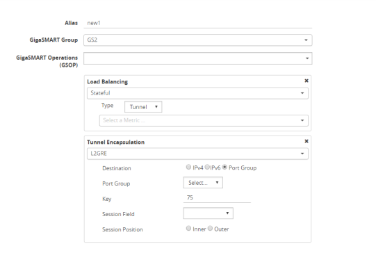
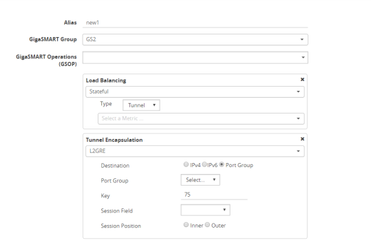
| 16. | Click New, then select the same GigaSMART Group and Tunnel Encapsulation for the GSOP. Under Load Balancing, select Stateful, the type Tunnel, and the metric, such as Round Robin. Under Tunnel Encapsulation, select L2GRE, Destination Port Group, select the Port Group, Session Field, and Session Position. Refer to Figure 1 New GigaSMART Operation for Stateful Load Balancing. |

| Figure 139 | New GigaSMART Operation for Stateful Load Balancing |
| 17. | Click OK. |
| 18. | Go to Maps > Maps. |
| 19. | Click New, then type an alias for the map, select type Regular and subtype ByRule. Under Map Source and Destination, select a network port as the Source and a tool port as the Destination, then select the GigaSMART operation. Under Map Rules, configure a map rule. Refer to Figure 2 New Map Configuration. |

| Figure 140 | New Map Configuration |
| 20. | Click OK. |
Example 3 configures stateless load balancing of tunnel traffic to tunnel endpoints based on a hash value.
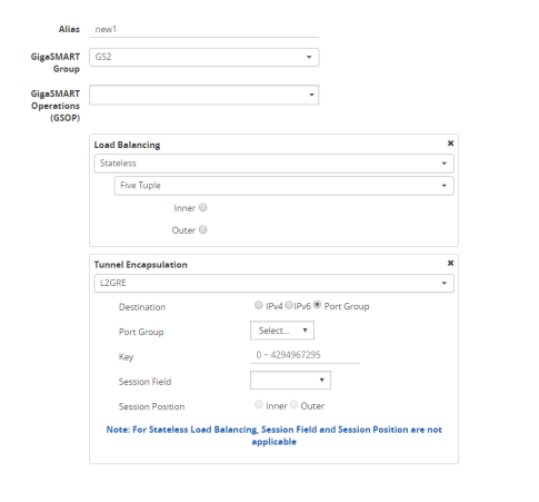
Example 3 has the same configuration steps as Example 2 except for the GigaSMART operation (gsop) in Step 16. Under Load Balancing, select Stateless and the metric, such as Five Tuple. Under Tunnel Encapsulation, select L2GRE, Destination Port Group, and select the Port Group. Refer to Figure 3 New GigaSMART Operation for Stateless.

| Figure 141 | New GigaSMART Operation for Stateless |
In this example, an IP interface is configured on the network port. A GigaSMART operation for tunnel decapsulation is configured to decapsulate the filtered packets. A map is configured that uses the L2GRE tunnel decapsulation GigaSMART operation, which receives packets from the remote site over the Internet to the main office using the IP interface associated with a tool port and then forwards packets over the tool port. Staring with software version 5.4 GigaSMART L2GRE Tunnel Decapsulation provides support for IPv6 with load-balancing.
|
Task |
Description |
UI Steps |
|||||||||||||||||||||||||||
|
Configure a network type of port and a tool type of port. |
|
|||||||||||||||||||||||||||
|
Configure a GigaSMART group and associate it with a GigaSMART engine port. |
|
|||||||||||||||||||||||||||
|
Configure the IP interface with an IP address, subnet mask, default gateway, and MTU setting. Assign it to the GigaSMART group. The IP address must match the destination IP address specified at the sending end of the tunnel. |
|
|||||||||||||||||||||||||||
|
Configure the GigaSMART operation for tunnel decapsulation and assign it to the GigaSMART group. The tunnel decapsulation settings include the GRE key that identifies the source of the tunnel. |
|
|||||||||||||||||||||||||||
|
Create a map using the tunnel decapsulation GigaSMART operation, with packets coming from the Internet through the network port and being sent to the local tool port. |
Select IP Version from the drop-down list and select v4 for Version, and then select Pass.
|
In this example, the encapsulation and decapsulation nodes are configured with IP interfaces using IPv6 addresses and load-balancing. IPv6 tunnel load-balancing feature supports the distribution of traffic across multiple IPv6 tunnel destination through the same tool port. Two types of load-balancing is supported, stateful and stateless.
To access GigaSMART within GigaVUE‑FM, access a device that has been added to GigaVUE‑FM from the GigaVUE‑FM interface. GigaSMART appears in the navigation pane of the device view on supported devices. Refer to Access GigaSMART from GigaVUE‑FM for details.
Create a map using the tunnel encapsulation GigaSMART operation, with packets coming from the network port and being sent to the Internet through the tool port.
| 1. | Select Ports > Ports > All Ports. |
| 2. | Click Quick Port Editor. |
| 3. | Use Quick search to find the ports to configure. |
| 4. | Set the type for each port and select Enable. |
| a. | type: tool - port 1/3/x7 |
| b. | type: network - 1/3/x8 |
| 1. | From the device view, select GigaSMART > GigaSMART Groups. |
| 2. | Click New. |
| 3. | Type an alias in the Alias field and enter an engine port in the Port List field. |
| 4. | Click OK. |
| 1. | Select Ports > IP Interfaces. |
| 2. | Click New. |
| 3. | In the Alias and Description fields, enter the name and description for the IP interface. |
| 4. | Click the Ports field and select the port from the drop-down list. |
| 5. | Select the Port address: IPv6 |
| 6. | Enter the IP address, subnet mask, gateway, and MTU settings in the respective fields. |
| 7. | From the GS Group drop-down list, select the required GigaSMART group. |
| 8. | Click OK. |
| 1. | From the device view, select GigaSMART > GigaSMART Operations > GigaSMART Operation. |
| 2. | Click New. |

| Figure 142 | GigaSMART Operation (GSOP) |
| 3. | In the Alias field, enter a name for the GigaSMART operation. |
| 4. | From the GigaSMART Group drop-down list, select the GigaSMARTGroup that you created in the step 2. |
| 5. | From the GigaSMART Operations (GSOP) drop-down list, select Tunnel Encapsulation. |
| 6. | Select L2GRE for the encapsulation type. |
| 7. | Enter the GRE key 123214 in the Key field. |
| 8. | Click OK. |
| 1. | Select Maps > Maps > Maps. |
| 2. | Click New. |

| Figure 143 | Map Configuration |
| 3. | Type an alias in the Map Alias field that will help you identify this map. |
| 4. | Select Regular and By Rule for the map type and subtype. |
| 5. | Specify the network and tool ports that you configured in step one in the Source and Destination fields, respectively. |
| 6. | From the GSOP drop-down list, select the GigaSMART operation configured in step 4. |
| 7. | Click Add a rule under Map Rules. |
| 8. | Select IP Version from the drop-down list and select v4 for Version. |
| 9. | Select Pass. |
| 10. | Click Add a rule under Map Rules and create the following rule: |
| 11. | Select IP Version from the drop-down list and select v6 for Version. |
| 12. | Select Pass. |
| a. | Source: From - 1/4x24 |
| b. | Destination: To: 1/4x7 |
| 13. | Click OK. |
On the decapsulation node, configure the receiving end of the tunnel
| 1. | Select Ports > Ports > All Ports. |
| 2. | Click Quick Port Editor. |
| 3. | Use Quick search to find the ports to configure. |
| 4. | Set the type for each port and select Enable. |
| a. | type: tool - port 1/4/x7 |
| b. | type: network - 1/4/x24 |
| 1. | From the device view, select GigaSMART > GigaSMART Groups. |
| 2. | Click New. |
| 3. | Type an alias in the Alias field and enter an engine port in the Port List field. |
| a. | engine port: 1/3/e1 |
| 4. | Click OK. |
| 1. | Select Ports > IP Interfaces. |
| 2. | Click New. |
| 3. | In the Alias and Description fields, enter the name and description for the IP interface. |
| 4. | Click the Ports field and select the port from the drop-down list. |
| 5. | Enter the IP address, subnet mask, gateway, and MTU settings in the respective fields. |
| 6. | From the GS Group drop-down list, select the required GigaSMART group. |
| 7. | Click OK. |
| 1. | From the device view, select GigaSMART > GigaSMART Operations > GigaSMART Operation. |
| 2. | Click New. |
| 3. | In the Alias field, enter a name for the GigaSMART operation. |
| 4. | From the GigaSMART Groups drop-down list, select the GigaSMART Group. |
| 5. | From the GigaSMART Operations (GSOP) drop-down list, select Tunnel Decapsulation. |
| 6. | Select L2GRE for the decapsulation type. |
| 7. | Enter the GRE key in the Key field. |
| 8. | Click OK. |
| 1. | Select Maps > Maps > Maps. |
| 2. | Click New. |
| 3. | Type an alias in the Map Alias field that will help you identify this map. |
| 4. | Select Regular and By Rule for the map type and subtype. |
| 5. | Specify the network and tool ports that you configured in task one in the Source and Destination fields, respectively. |
| 6. | From the GSOP drop-down list, select the GigaSMART operation. |
| 7. | Click Add a rule under Map Rules and create the following rule: |
| 8. | Select IP Version from the drop-down list and select v4 for Version. |
| 9. | Select Pass. |
| 10. | Click Add a rule under Map Rules and create the following rule: |
| 11. | Select IP Version from the drop-down list and select v6 for Version. |
| 12. | Select Pass. |
| a. | Source: From - 1/4x24 |
| b. | Destination: To: 1/4x7 |
| 13. | Click OK. |


