About Inline Networks
Currently configured in-line networks are displayed on the Inline Networks page, which is opened by selecting Inline Bypass > Inline Networks.
Click New to open the Inline Network configuration page to configure an inline network, which is a pair of network ports arranged for inline monitoring. The arrangement facilitates access to a bidirectional link between the two networks (two far-end network devices) that need to be linked through an inline tool.
An inline network consists of inline network ports, always in pairs, running at the same speed, on the same medium (either fiber or copper). The inline network ports must be on the same GigaVUE‑HC3, GigaVUE‑HC2, or GigaVUE‑HC1 node.
An inline network can be unprotected or protected. On the GigaVUE HC Series nodes, protected inline networks are implemented using bypass combo modules. Protected inline networks are based on the pairs of ports associated with physical protection switches on the bypass combo modules. The protected inline network ports provided by the bypass combo modules offer link speeds that can be configured at either 1Gb or 10Gb.
Starting in software version 5.0, the GigaVUE‑HC2 with Control Card version 2 supports a 40Gb bypass combo module and starting in software 5.1.01, the GigaVUE‑HC3 supports a 100Gb bypass combo module and starting in software version 5.2, the GigaVUE‑HC3 100Gb bypass combo module supports dual speeds: 100Gb or 40Gb.
Note: You do not need to create the inline network ports for the protected port pairs on the bypass combo modules because they are created automatically when the bypass combo module initializes.
Other ports on the bypass combo module or on other line cards or modules can be designated as inline-network type ports. These ports will automatically be unprotected.
You also do not need to create the protected inline networks on the bypass combo modules because they are created automatically when the bypass combo module initializes. In addition, you cannot delete the protected inline networks on the bypass combo modules.
On GigaVUE‑HC1, inline networks can also be configured on the copper TAP-HC1-G10040 module. On the GigaVUE‑HC2, inline networks can be configured on the copper TAP-HC0-G100C0 module.
Once an inline network is created, it is fully configurable regardless of whether or not it is associated with an inline tool or an inline tool group through a map or map passall.
Use the Inline Networks page to display the configuration of inline networks as well as the current state of the inline bypass solution. The overall state of the inline bypass solution consists of the inline networks involved in the solution as well as the associated inline maps and inline tools. For details, refer to the following:
| Display Current State of Inline Bypass Solution |
| How to Use SNMP Polling to Obtain Inline Network State |
| SNMP Notification of Forwarding State Change |
| How to Use Syslog to Obtain Inline Network State |
For details on the parameters of inline networks, refer to the following:
| Network Port Link Status Propagation Parameter |
| Traffic Path Parameter |
| Physical Bypass Parameter. |
Network Port Link Status Propagation Parameter
One of the parameters of inline networks is link status propagation, which controls the behavior of the link status for the inline network ports involved in a given inline network. The default is enabled.
When enabled, an inline network link failure on one side of the inline network will be propagated to the other side. For example, when the link is lost on one side of the network such that traffic cannot be sent to the inline tools, the link on the opposite side of the network is also brought down.
When the link is restored to the side that originally went down, the link will automatically be restored to the other side of the network. The GigaVUE node will not forward packets to the inline tools until the link is restored on both sides.
Link status propagation is enabled by selecting Link Failure Propagation when configuring an inline network port.
Traffic Path Parameter
One of the parameters of inline networks is Traffic Path, which specifies the path of the traffic received at an inline network port. The values are as follows:
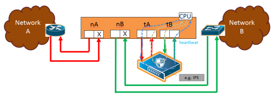
| Drop—no traffic is exchanged through the inline network ports. All traffic to these ports is dropped. No traffic is forwarded to or from the inline tool or tools. No traffic is passed from inline network port A to inline network port B or from inline network port B to inline network port A. Refer to Figure 1 Traffic Path of Drop. |
| ByPass—there are two cases for bypass as follows, depending on the inline map configuration: |
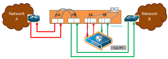
| If there are no inline maps associated with the inline network or if the set of inline maps associated with the inline network guarantees that no traffic is dropped when the traffic path is set to To Inline Tool, then setting the traffic path to Bypass leads to the following: all traffic arriving at the side A inline network port is forwarded to the side B inline network port and all traffic arriving at the side B inline network port is forwarded to the side A inline network port through a logical bypass. Refer to Figure 2 Traffic Path of Bypass for a simple scenario involving a map-passall in which there is no possibility of traffic drops. |
| If the set of inline maps associated with the inline network involves some traffic drop when the traffic path is set to To Inline Tool, then setting the traffic path to Bypass leads to the following: all traffic arriving at the side A inline network port that would not have been dropped with traffic path set to To Inline Tool is forwarded to the side B inline network port and all traffic arriving at the side B inline network port that would not have been dropped with traffic path set to To Inline Tool is forwarded to the side A inline network port through a logical bypass. In other words, packets that were dropped when the traffic path was set to To Inline Tool will also be dropped when set to Bypass. |
In either of these two bypass cases, no traffic is forwarded to the inline tool or tools.
| ByPass with Monitoring—there are two cases for monitoring as follows, depending on the inline map configuration: |
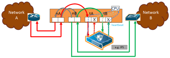
| If there are no inline maps associated with the inline network or if the set of inline maps associated with the inline network guarantees that no traffic is dropped when the traffic path is set to To Inline Tool, then setting the traffic path to ByPass with Monitoring leads to the following: all traffic is forwarded as for bypass, but a copy of the traffic is forwarded to the inline tool or tools according to the configured maps between the inline network and the inline tool or tools. Refer to Figure 3 Traffic Path of Monitoring for a simple scenario involving a map-passall in which there is no possibility of traffic drops. |
| If the set of inline maps associated with the inline network involves some traffic drop when the traffic path is set to To Inline Tool, then setting the traffic path to ByPass with Monitoring leads to the following: all traffic that would not have been dropped with traffic path set to To Inline Tool is forwarded as for bypass, but a copy of the traffic is forwarded to the inline tool or tools according to the configured maps between the inline network and the inline tool or tools. |
In either of these two monitoring cases, no traffic is taken from the inline tools.
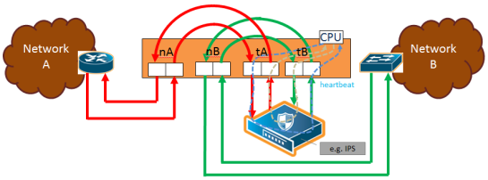
| To Inline Tool—traffic received at the inline network ports is forwarded according to the following factors: |
| the configured maps between the inline network and the inline tools |
| the failover actions of the inline tool or tools |
| the health state of the inline tool or tools |
Refer to Figure 4 Traffic Path of To-Inline-Tool.
The default is Bypass. This avoids any traffic loss when first configuring an unprotected inline network or when disabling physical bypass on a protected inline network.
Figure 1 to Figure 4 show the traffic path for a simple inline bypass solution with inline network ports (nA and nB), inline tool ports (tA and tB), and a map passall.

| Figure 64 | Traffic Path of Drop |

| Figure 65 | Traffic Path of Bypass |

| Figure 66 | Traffic Path of Monitoring |

| Figure 67 | Traffic Path of To-Inline-Tool |
Physical Bypass Parameter
One of the parameters of inline networks is physical bypass, which controls the state of the optical protection switch on the bypass combo module or copper TAP module when the module is powered on. The optical protection switch can have one of the following states:
| close—the fiber connected to the side A network port is passively coupled with the fiber connected to the side B port without any transceivers or switching fabric. Therefore, any traffic coming in on these fibers is exchanged between the two inline network ports without being noticed by the system. |
| open—the fiber connected to the inline network ports is coupled through transceivers with the switching fabric that is under software control. Therefore, any traffic coming in on these fibers is subject to the traffic forwarding rules imposed by the current configuration as well as the current state of the inline tools. |
When the bypass combo module or copper TAP modules is powered off, the optical protection switch is always in the close state.
When the bypass combo module or copper TAP modules is powered on, the state of the optical protection switch is as follows:
| the close state if Physical Bypass is set to enable (that is, selected on the configuration page) |
| the open state if physical bypass is set to disable (that is, not selected on the configuration page) |
Physical Bypass is enabled by default.
Note: Physical bypass only applies to protected inline networks.
Redundancy Profile Parameter
One of the parameters of inline networks is redundancy profile. A redundancy profile is used to configure Gigamon Resiliency for Inline Protection (GRIP). For more detailed information about GRIP, refer to the Configure Gigamon Resiliency for Inline Protection.
To created a redundancy profile, doing the following:
| 1. | Select Inline Bypass > Redundancies. |
| 2. | Click New to open the Add Redundancy Profile page. |
| 3. | Type a name for the profile in the Alias field to help identify the profile. |
| 4. | Select a stack port by clicking the Signaling Port field and selecting an available port. |
The Signaling Port field specifies the used to signal the state of the two GigaVUE‑HC2 nodes to each other. The ports provide the mechanism to detect loss of power in one of the GigaVUE‑HC2 nodes.
| 5. | Click in the Protection Role field and select a role. |
The protection role specifies the role of the GigaVUE‑HC2, as primary, secondary, or suspended. The default is suspended. When suspended, the protection role is on hold. Changing a GigaVUE‑HC2 from the primary role to the suspended role can be used to manually force one of the GigaVUE‑HC2 nodes to become active. The suspended role is also used when performing maintenance.
| 6. | Click Save. |
To add the redundancy profile to the inline network, select the profile from the Redundancy Profile drop-down list on the Inline Network configuration page.
Display Current State of Inline Bypass Solution
Inline networks, inline tools, and inline maps work together to form an inline bypass solution. The inline bypass solution has an overall state, which can change in response to hardware conditions and user configuration.
Several factors make up the overall state of an inline bypass solution, as follows:
| The physical bypass configuration of the inline network is protected. |
| The inline network configuration, in particular, if physical bypass is enabled or disabled, what traffic path is configured, and if link failure propagation is enabled or disabled. |
| The inline tool configuration, in particular, if the state of the inline tool is enabled or disabled, if there is a heartbeat profile configured and if the heartbeat is enabled or disabled, and what failover actions are configured. |
| The inline tool group configuration, in particular, if the state of the inline tool group is enabled or disabled, what failover mode is configured, what failover action is configured, and what number of minimum healthy tools is configured. |
| The status of the links attached to the inline network ports and inline tool ports. |
Forwarding States and Determining Factors describes each forwarding state and the factors determining that state.
Whenever link failure propagation is configured as false (disabled), the inline network port status reflects the status of the respective far-end ports. Only when link failure propagation is configured as true (enabled) does this behavior change. Refer to the note under the Forwarding states for DISABLED and DISCONNECTED in Forwarding States and Determining Factors.
|
physical-bypass |
traffic-path |
Status of far-end ports connected to inline network ports |
Status of inline tool side |
Description |
|
enable |
drop, bypass, monitoring, or to-inline-tool |
any status |
any status |
Forwarding state—PHYSICAL BYPASS If physical bypass is enabled, all traffic is exchanged directly between side A network and side B network without any monitoring by the GigaVUE node. Only applies to protected inline networks. |
|
disable |
drop |
any status |
any status |
Forwarding state—DISABLED If the inline network is configured with a traffic path of drop, no traffic is exchanged between side A network and side B network because all packets coming to the inline network ports are dropped. Note: If the inline network is configured with link failure propagation set to true (enabled), the status of the inline network ports will be determined by the status of the far-end ports connected to the inline network ports. If both far-end ports are up, then both inline network ports will be up. If any far-end ports are down, then both inline network ports will be down. |
|
disable |
bypass, monitoring, or to-inline-tool |
at least one far-end port is down |
any status |
Forwarding state—DISCONNECTED When one of the inline network ports is down due to a link down caused by a far-end device, no traffic is exchanged between side A network and side B network. Note: If the inline network is configured with link failure propagation enable as true, the status of both inline network ports will be down. That is, if only one inline network port is down, the other will be brought down. |
|
disable |
bypass |
both far-end ports are up |
any status |
Forwarding state—FORCED BYPASS If the inline network is configured with a traffic path of bypass, all traffic that would not have been dropped when the traffic path is set to to-inline-tool is exchanged directly between side A network and side B network through the switching fabric. |
|
disable |
monitoring |
both far-end ports are up |
any status |
Forwarding state—FORCED BYPASS WITH MONITORING If the inline network is configured with a traffic path of monitoring, all traffic that would not have been dropped when the traffic path is set to to-inline-tool is exchanged directly between side A network and side B network through the switching fabric. If there is any inline map configured for the inline network, a copy of the respective traffic is directed to the respective inline tools according to the configured inline maps. |
|
disable |
to-inline-tool |
both far-end ports are up |
all inline tools involved in the inline bypass solution are operating as expected |
Forwarding state—NORMAL If all inline tools involved in the inline bypass solution are enabled, all inline tool ports are up, and the inline tools operating with heartbeat protocol enabled have a heartbeat status of up, traffic flows as desired according to the configuration of the inline maps. Note: If there are no inline maps, setting the traffic path of a protected fiber inline network to to-inline-tool results in a NORMAL forwarding state, but the traffic sent to the source inline network ports will be dropped because there are no inline maps specifying destination tool ports to which to forward the traffic.
|
|
disable |
to-inline-tool |
both far-end ports are up |
at least one inline tool involved in the inline bypass solution is disabled or associated with any inline tool port that is down or associated with the heartbeat protocol in a down state |
Forwarding state—FAILURE-INTRODUCED BYPASS All traffic is exchanged directly between side A network and side B network through the switching fabric as a result of an inline tool port failure or heartbeat failure or inline tool being disabled that led to the network-level bypass due to the configured failover actions. |
|
disable |
to-inline-tool |
both far-end ports are up |
at least one inline tool involved in the inline bypass solution is disabled or associated with any inline tool port that is down or associated with the heartbeat protocol in a down state |
Forwarding state—FAILURE-INTRODUCED DROP No traffic is exchanged between side A network and side B network. All packets coming to the inline network ports are dropped as a result of an inline tool port failure or heartbeat failure or inline tool being disabled that led to the network-level drop due to the configured failover actions. |
|
disable |
to-inline-tool |
both far-end ports are up |
at least one inline tool involved in the inline bypass solution is disabled or associated with any inline tool port that is down or associated with the heartbeat protocol in a down state |
Forwarding state—NETWORK PORTS FORCED DOWN No traffic is exchanged between side A network and side B network. The inline network ports are forced down as a result of an inline tool port failure or heartbeat failure or inline tool being disabled that led to the network ports being forced down due to the configured failover actions. |
|
disable |
to-inline-tool |
both far-end ports are up |
at least one inline tool involved in the inline bypass solution is disabled or associated with any inline tool port that is down or associated with the heartbeat protocol in a down state |
Forwarding state—ABNORMAL Any condition of the inline bypass solution that does not meet the criteria of the forwarding states listed in this table. At least one inline tool passes traffic as desired. There are many scenarios that can lead to the abnormal forwarding state, for example, when one inline tool member of an inline tool group has failed, but the number of remaining healthy tools is still above the minimum required number of healthy tools. |
How to Use SNMP Polling to Obtain Inline Network State
The overall inline network state can also be obtained through SNMP polling using an SNMP-compliant network management application or a MIB browser. The names of the MIB files that need to be loaded in order to poll the inline network state are: GIGAMON-COMMON-SMI and GIGAMONINLINEBYPASS.
The inline network forwarding states are described in Forwarding States and Determining Factors. Some of the states have slightly different names in SNMP.
SNMP Notification of Forwarding State Change
Use the following steps to configure a notification that will be sent when the inline bypass forwarding state changes:
| 1. | Select Settings > SNMP Traps. |
| 2. | Click Trap Settings. The Edit SNMP Trap Settings page displays. |
| 3. | On the Edit SNMP Trap Settings page, select Enable for Inline Bypass Forwarding State Change. |
| 4. | Click Save. |
How to Use Syslog to Obtain Inline Network State
The overall inline network state can also be obtained through syslog.
When the inline network state change is triggered by a configuration change, a sample syslog message is as follows:
IBFE STATE CHANGE inline network default_inline_net_1_1_1 status NORMAL changed to PHYSICAL BYPASS triggered by config
When the inline network state change is triggered by a link status change or heartbeat status change, a sample syslog message is as follows:
IBFE STATE CHANGE inline network inNet1 status NORMAL changed to FAILURE INTRODUCED BYPASS triggered by 1/x10
In the syslog messages, IBFE indicates the Inline Bypass Failover Engine.
The inline network forwarding states are described in Forwarding States and Determining Factors.


