GigaSMART Application Session Filtering (ASF) and Buffer ASF
Required Licenses: Adaptive Packet Filtering (APF) and Application Session Filtering (ASF)
NOTE: The ASF license requires the APF license to be installed as a prerequisite.
Deprecation Announcement: GigaSMART Application Session Filtering is end-of-sale in 5.6.00. Refer to the Application Intelligence to learn about the feature set and licensing for the improved application filtering and application metadata functionality.
Application Session Filtering (ASF) provides additional filtering on top of Adaptive Packet Filtering (APF). With APF, you can filter on any data patterns within a packet. With ASF, you apply the pattern matching and then send all the packet flows associated with the matched packet to monitoring or security tools.
ASF allows you to filter all traffic corresponding to a session. Use ASF to create a flow session and send the packets associated with the flow session to one or more tools. A flow session consists of one or more fields that you select to define the session. Either the packets for the whole session can be captured or only the packets following a pattern match.
A flow session is a session defined by protocol fields in the packet. For example, you can define a flow session with source and destination IP (two tuple), source and destination IP plus source and destination port (four tuple), or any combinations with inner or outer IP/port and protocol.
For example, use APF to filter TCP packets to capture the SYN packet. Then use ASF with GigaSMART Load Balancing to send all subsequent packets associated with the session to multiple tool ports. This example is illustrated in Example 1: ASF, Forward TCP Traffic. For information on capturing a whole session by buffering packets, refer to Application Session Filtering with Buffering.
Or use APF to create pattern-matching filters in which the pattern is a sequence of data bytes at a variable or fixed offset within a packet. Then use ASF with a specified session definition to capture subsequent packets belonging to the session. When an incoming packet matches an APF rule, a flow session is created. The subsequent incoming packets that match the value of the fields in the flow session will be forwarded to the same tool port as the matching packet.
For example, use APF to pattern match the string www.gigamon.com. Use the 5tuple field to identify the flow session. This creates the signature of the session. All the packets associated with the session will be forwarded to a tool port, hence APF becomes flow-aware or session-aware.
ASF provides the following session capabilities:
|
•
|
filter on one, two, or both MPLS labels and/or VLAN IDs |
|
•
|
filter on both inner and outer IP addresses, Layer 4 ports, and protocols |
Pattern matching examples are illustrated in Pattern Match with Type String to Example 4: ASF, Forward GTP Traffic
For information on load balancing, refer to stateful load balancing in the section GigaSMART Load Balancing.
ASF operations can be assigned to GigaSMART groups consisting of multiple engine ports. Refer to Groups of GigaSMART Engine Ports for details.
In ASF and buffer ASF second level maps, a maximum of five (5) maps can be attached to a virtual port (vport). Each map can contain up to 25 gsrules.
Application Session Filtering (with or without buffering) is a pillar of the GigaSECURE Security Delivery Platform. Refer to GigaSECURE Security Delivery Platform.
Session-Aware APF (SAPF) Renaming and Licensing Change to ASF
The GigaSMART feature named Session-Aware Adaptive Packet Filtering (SAPF) in GigaVUE-OS 4.3 was renamed to Application Session Filtering (ASF) in GigaVUE-OS 4.4. It is now encompassed within ASF as the non-buffering equivalent to Application Session Filtering with buffering.
In addition, the license has moved from the APF license to the ASF license.
Application Session Filtering with Buffering
ASF captures packets of a session after an APF rule match. When the APF match occurs in the middle of a session, packets in the session prior to the match are not captured. With some tools needing all the packets of a flow session in order to perform data analysis, GigaSMART uses buffering to ensure that all packets belonging to a flow session are captured and forwarded to the tools. This is referred to as Application Session Filtering with buffering, or buffer ASF.
Buffer ASF uses the pattern-matching and regular expression engine in APF to select packet flows based on matching criteria with one or more packets in the flow session. Buffering ensures that the entire session, from start to finish, is either dropped or forwarded to the security tools or the performance monitoring tools.
To capture all packets belonging to a flow session prior to the APF rule match, ASF needs to know the first packet of a flow session. For this, GigaSMART supports both TCP and UDP connections.
For TCP connections, the TCP SYN packet is used to indicate the start of a session. GigaSMART captures and stores (or buffers) all packets of a flow session until an APF match occurs. After that, GigaSMART will either forward or drop all stored packets belonging to that session based on the APF pass or drop rule that is configured. Subsequent packets after the APF match will be forwarded or dropped as they arrive.
For UDP connections, there is no special packet that indicates the start of a UDP flow session from a Layer 4 perspective. GigaSMART will take the first UDP packet of a session it encounters as the start of a session flow. This may result in incomplete capture at the beginning of configuration or at system boot up, but as new UDP sessions arrive, GigaSMART will capture the first packet of the flows.
ASF and Buffer ASF Session Definitions
Use the Session Field of the ASF page to define ASF and buffer ASF sessions by specifying session field attributes to add or delete. A session field is a group of one or more fields that define a flow session. (From the device view, select GigaSMART > ASF and click New to open the ASF page.)
A flow session consists of field names and attributes. Some field names include multiple attributes, which provide a quick way to define sessions.
The field names and attributes are as follows:
|
•
|
ipv4 (ipv4-src, ipv4-dst) |
|
•
|
ipv4-5tuple (ipv4-src, ipv4-dst, l4port-src, l4port-dst, ipv4-protocol) |
|
•
|
ipv4-l4port-dst (ipv4-src, ipv4-dst, l4port-dst) |
|
•
|
ipv4-src-l4port-dst (ipv4-src, l4port-dst) |
|
•
|
ipv6 (ipv6-src, ipv6-dst) |
|
•
|
ipv6-5tuple (ipv6-src, ipv6-dst, l4port-src, l4port-dst, ipv6-protocol) |
|
•
|
ipv6-l4port-dst (ipv6-src, ipv6-dst, l4port-dst) |
|
•
|
ipv6-src-l4port-dst (ipv6-src, l4port-dst) |
|
•
|
l4port (l4port-src, l4port-dst) |
An ASF session definition consists of combinations of the fields and attributes in the list above. In addition, for all IP and L4 port fields in the packet, each ASF session field must specify outer or inner for location. Outer specifies the first IP or L4 port in the packet. Inner specifies the second IP or L4 port in the packet (usually inside tunneling). For VLAN ID and MPLS label fields, a position (1 or 2) must be specified. Position 1 is the first occurrence of the protocol header or field in the packet. Position 2 is the second occurrence of the protocol header or field in the packet.
A buffer ASF session definition consists of combinations of the fields and attributes in the list above. One restriction is that ipv4-src or ipv6-src needs to be defined, as a minimum. In addition, the following restrictions apply to buffer ASF session definitions:
|
•
|
the gtpu-teid field name is not supported |
|
•
|
the IP and L4 port fields only support location outer |
|
•
|
the VLAN ID field only supports position 1 |
All packets belonging to the same source and destination IP will be considered as the same flow session. This is useful if you want to capture all packets belonging to separate TCP/UDP connections that have the same IPs, such as control or data flows.
Define ASF Session
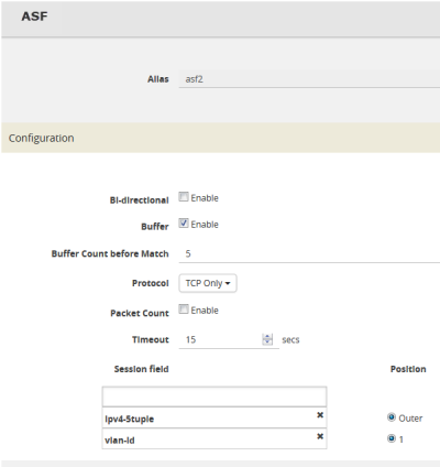
When defining an ASF session, enter the fields, attributes, and options, then save. The changes only take effect when after you save. For example, in Figure 1: An ASF Configuration, the settings are:
|
•
|
Alias is asf2, which is name of the ASF Profile for the GigaSMART Operation |
|
•
|
Buffer Count before Match is 5 |
|
Figure 3
|
An ASF Configuration |
Quick Session Delete for Buffer ASF
For a buffer ASF session defined with ipv4-5tuple or ipv6-5tuple, there is a quick session delete for TCP connections. The session is deleted 4 seconds after RST or both FIN packets are detected, signaling the end of the flow.
Specify Resources for Buffer ASF
On GigaVUE-HC3, GigaVUE-HC2, and GigaVUE‑HC1 nodes buffer ASF supports from 2 to 5 million sessions.
The large number of sessions can use a lot of memory resources on the GigaSMART line card or module. Occasionally, the GigaSMART line card or module will need to be reloaded for changes to take effect and to allocate resources accordingly.
The GigaSMART line card or module does not need to be reloaded the first time buffer ASF resources are allocated. But subsequent changes, such as increasing from 3 million to 4 million sessions, or decreasing from 3 million to 2 million sessions will require a reload for the changes to take effect.
You can reload the card from the UI, by doing the following:
|
1.
|
On the top navigation bar, click Inventory, and then select the required cluster or node ID.
|
|
2.
|
From the left navigation pane, go to System > Chassis.
|
|
3.
|
Clicking the Table View button to open the Table View of the Chassis. |
|
4.
|
Under Cards, select the card to reload. |
|
5.
|
From the Actions menu, select Shut Down. |
|
6.
|
Now select Start Up from Actions menu. |
Alternatively, you can use the following GigaVUE-FM API to reload the card:
PATCH /inventory/chassis/cards/{slotId}
For more information about the GigaVUE-FM APIs, refer to the GigaVUE-FM REST API Reference in GigaVUE-FM User's Guide.
You can also reload the card with the following two CLI commands:
(config) # card slot <slot ID> down
(config) # no card slot <slot ID> down
For more information about the CLI commands, refer the GigaVUE-OS-CLI Reference Guide.
ASF and Buffer ASF Session Notes
The following table summarizes notes relating to ASF and buffer ASF:
|
Notes
|
|
A session field can only be modified or deleted if it is not configured in any GigaSMART operation.
|
|
A session field can only contain the same session attribute and position pair once.
|
|
A session field cannot contain overlapped session attribute and position. For example, the following is not valid: ipv4-5tuple outer and ipv4-src outer.
|
|
Up to a maximum of 25 flow session aliases are supported for ASF.
|
|
A total of 4 session tables per GigaSMART engine are supported for ASF. Each table has its own session definition.
|
|
Up to 2 million session entries are supported for ASF. The entries are shared by all session aliases.
|
|
Each session table (session alias) can only be used once within a gsgroup.
|
|
The number of buffer ASF sessions supported is configurable from 2 to 5 million.
|
|
The number of packet buffers supported for buffer ASF is from 2 to 5 million.
|
Buffer ASF Packet Processing Special Cases
The following are special cases of packet processing for buffer ASF:
|
•
|
Non-TCP SYN packet received and no session matched—When a non-TCP SYN packet is received and there is no session matched, the packet will be considered as no match and will be passed to other maps. If there is no match after all maps have been processed, the packet will be forwarded to a shared collector, if one is configured. |
|
•
|
Out of session—When a TCP SYN packet is received and no free session is available, the packet will be considered as no match. Other packets belonging to this session will also be considered as no match, as for the special case described above. |
|
•
|
Out of packet storage buffer—When the buffer is full for the first packet of a session, the session will not be created and the packet will be considered as no match. When the buffer is full for an existing session, and the APF match has not yet occurred, a flag will be set and the current packet and all buffered packets will be considered as no match. Subsequent packets will also be considered as no match. |
|
•
|
Exceeded configured buffering limit—When there is no APF match after the configured number of packets have been buffered, all buffered packets and all subsequent packets belonging to this session will be considered as no match. |
Map Statistics
Go to Map > Statistics to display counts of the rules that actually matched in a map. A single packet can match one or more rules. For example, if a single packet matches multiple rules in an ASF or buffer ASF map, all matching rules will have that packet counted against them and the overall map status pass counter will show 1.
ASF and Buffer ASF Examples
Refer to the following ASF examples (non-buffered):
Refer to the following buffer ASF examples:
Example 1: ASF, Forward TCP Traffic
In Example 1, ASF is used with GigaSMART Load Balancing and Adaptive Packet Filtering to load balance TCP traffic among multiple tool ports. TCP SYN indicates the start of a connection. Once the TCP SYN packet is detected, subsequent packets belonging to the same TCP connection will be forwarded to a configured tool port. Packets belonging to the same connection will be sent to the same tool port, regardless of the number of connections.
Note: This example uses APF to filter TCP packets to capture the SYN packet. Alternatively, use buffer ASF to capture a whole session by buffering packets.
|
Task
|
Description
|
UI Steps
|
|
1
|
Create a flow session.
|
|
1.
|
From the device view, select GigaSMART > ASF. |
|
3.
|
Type asf4 in the Alias field. |
|
4.
|
Select ipv4-tuple from the Session field list. |
|
|
2
|
Create a port group and specify the tool ports for load balancing.
|
|
1.
|
Select Ports > Port Groups > All Port Groups. |
|
3.
|
Type portgrp1 in the Alias field. |
|
5.
|
Select SMART Load Balancing. |
|
6.
|
Click in the Ports field and select the tool ports. For example, 1/1/x6,1/1/x7,1/2/x3, and 1/2/x4. |
|
|
3
|
Configure a GigaSMART group and associate it with GigaSMART engine ports.
|
|
1.
|
From the device view, select GigaSMART > GigaSMART Groups > GigaSMART Groups. |
|
3.
|
Type gsgrp1 in the Alias field. |
|
4.
|
Select two engine ports from the Port List field. For example, 1/3/e1 and 1/3/e2 |
|
|
4
|
Configure the combined GigaSMART operation.
|
|
1.
|
From the device view, select GigaSMART > GigaSMART Operations (GSOP) > GigaSMART Operation and create two GigaSMART Operations. |
|
3.
|
Type gsop1 in the Alias field. |
|
4.
|
Select gsgrp1 from the GigaSMART Groups list. |
|
5.
|
Select the operations. |
|
•
|
ASF with asf4 for the ASF profile |
|
•
|
Load Balancing with Stateful Type ASF, and Round Robin |
|
|
5
|
Create a virtual port and associate it with the GigaSMART group.
|
|
1.
|
From the device view, select GigaSMART > Virtual ports. |
|
3.
|
Enter vp1 in the Alias field. |
|
4.
|
Select gsg1 from the GigaSMART Groups list. |
|
|
6
|
Create a first level map.
|
|
1.
|
Select Maps > Maps > Maps. |
|
a.
|
Type map11 in the Alias field. |
|
b.
|
Select First Level for Type. |
|
c.
|
Select By Rule for Subtype. |
|
d.
|
Select the network port 1/1/x1 for the Source. |
|
e.
|
Select the virtual port vp1 for the Destination. |
|
c.
|
Select IPv4 Version and set version to 4 |
|
|
7
|
Create a second level map. The gsrule captures the first packet of a session.
|
|
a.
|
Type map22 in the Alias field. |
|
b.
|
Select Second Level for Type. |
|
c.
|
Select By Rule for Subtype. |
|
d.
|
Select the virtual port vp1 for the Source. |
|
e.
|
Select the port group portgrp1 for the Destination. |
|
f.
|
Select gsop1 form the GSOP list. |
|
Example 2: ASF, Forward VNC Traffic
In Example 2, traffic from a Virtual Network Computing (VNC) application is forwarded from network port 1/1/x1 to tool port 1/1/x6. Packets will be matched with a VNC signature. Once a packet is matched, subsequent packets with the same IPv4 5tuple will be forwarded to the same destination as the matching packet. By default, both the forward and the reverse traffic of the same session will be captured and forwarded.
|
Step
|
Description
|
Command
|
|
1
|
Create a flow session.
|
|
1.
|
From the device view, select GigaSMART > ASF. |
|
3.
|
Type asf1 in the Alias field. |
|
4.
|
Select ipv4-tuple from the Session field list. |
|
|
2
|
Configure a GigaSMART group and associate it with GigaSMART engine ports.
|
|
1.
|
From the device view, select GigaSMART > GigaSMART Groups > GigaSMART Groups. |
|
3.
|
Type gsgrp1 in the Alias field. |
|
4.
|
Select two engine ports from the Port List field. For example,
1/3/e1 and 1/3/e2 |
|
|
3
|
Configure the combined GigaSMART operation.
|
|
1.
|
From the device view, select GigaSMART > GigaSMART Operations (GSOP) > GigaSMART Operations and create two GigaSMART Operations. |
|
3.
|
Type gsop1 in the Alias field. |
|
4.
|
Select gsgrp1 from the GigaSMART Groups list. |
|
5.
|
Select the operations. |
|
•
|
ASF with asf1 for the ASF profile |
|
|
4
|
Create a virtual port and associate it with the GigaSMART group.
|
|
1.
|
From the device view, select GigaSMART > Virtual ports. |
|
3.
|
Enter vp1 in the Alias field. |
|
4.
|
Select gsgrp1 from the GigaSMART Groups list. |
|
|
5
|
Create a first level map.
|
|
1.
|
Select Maps > Maps > Maps. |
|
a.
|
Type map11 in the Alias field. |
|
b.
|
Select First Level for Type. |
|
c.
|
Select By Rule for Subtype. |
|
d.
|
Select the network port 1/1/x1 for the Source. |
|
e.
|
Select the virtual port vp1 for the Destination. |
|
c.
|
Select IPv4 Version and set Version to 4 |
|
|
6
|
Create a second level egress map. The gsrule contains the VNC signature.
|
|
a.
|
Type map22 in the Alias field. |
|
b.
|
Select Second Level for Type. |
|
c.
|
Select By Rule for Subtype. |
|
d.
|
Select the virtual port vp1 for the Source. |
|
e.
|
Select the port group portgrp1 for the Destination. |
|
f.
|
Select gsop1 form the GSOP list. |
|
d.
|
Select regex for Type and enter ^rfb 00[1-9]\.00[0-9]\x0a$ |
|
e.
|
Set Offset from 16 to 1000 |
|
Example 3: ASF, Forward Traffic Matching a Pattern
In Example 3, the traffic that matches a particular pattern (ymsg|ypns|yhoo) is forwarded from network port 1/1/x1 to tool port 1/1/x6 after adding a VLAN tag. Packets will be matched with the special signature. Once a packet is matched, subsequent packets with the same source IP, source port, and VLAN ID will be forwarded to the same destination as the matching packet (after the VLAN header is inserted). By default, both the forward and the reverse traffic of the same session will be captured and forwarded.
|
Task
|
Description
|
UI Steps
|
|
1
|
Create a flow session and other parameters.
|
|
1.
|
From the device view, select GigaSMART > ASF. |
|
3.
|
Type asf2 in the Alias field. |
|
5.
|
Set Number of packets to 50. |
|
6.
|
Set the session field. |
|
•
|
Select vlan-id position 1 |
|
|
2
|
Configure a GigaSMART group and associate it with GigaSMART engine ports.
|
|
1.
|
From the device view, select GigaSMART > GigaSMART Groups > GigaSMART Groups. |
|
3.
|
Type gsgrp1 in the Alias field. |
|
4.
|
Select two engine ports from the Port List field. For example,
1/3/e1 and 1/3/e2 |
|
|
3
|
Configure the GigaSMART operation.
|
|
1.
|
From the device view, select GigaSMART > GigaSMART Operations (GSOP) > GigaSMART Operation and create two GigaSMART Operations. |
|
3.
|
Type gsop1 in the Alias field. |
|
4.
|
Select gsgrp1 from the GS Groups list. |
|
5.
|
Select the operations. |
|
•
|
Adaptive Packet Filtering |
|
•
|
Add Header and set VLAN to 1000 |
|
•
|
ASF with asf2 for the ASF profile |
|
|
4
|
Create a virtual port and associate it with the GigaSMART group.
|
|
1.
|
From the device view, select GigaSMART > Virtual ports. |
|
3.
|
Enter vp1 in the Alias field. |
|
4.
|
Select gsgrp1 from the GigaSMART Groups list. |
|
|
5
|
Create a first level map.
|
|
1.
|
Select Maps > Maps > Maps. |
|
a.
|
Type map11 in the Alias field. |
|
b.
|
Select First Level for Type. |
|
c.
|
Select By Rule for Subtype. |
|
d.
|
Select the network port 1/1/x1 for the Source. |
|
e.
|
Select the virtual port vp1 for the Destination. |
|
c.
|
Select IPv4 Version and set Version to 4 |
|
|
6
|
Create a second level map. The gsrule contains the special signature.
|
|
a.
|
Type map22 in the Alias field. |
|
b.
|
Select Second Level for Type. |
|
c.
|
Select By Rule for Subtype. |
|
d.
|
Select the virtual port vp1 for the Source. |
|
e.
|
Select the too port 1/1/x6 for the Destination. |
|
f.
|
Select gsop1 form the GSOP list. |
|
d.
|
Select regex for Type and enter (ymsg|ypns|yhoo) |
|
e.
|
Set Offsett from 16 to 1000 |
|
Example 4: ASF, Forward GTP Traffic
In Example 4, GTP traffic from network port 1/1/x1 is load balanced based on inner IP and tunnel ID to four tool ports: 1/1/x6, 1/1/x7, 1/2/x3, and 1/2/x4. APF filters GTP-u packets. Once a packet is matched, subsequent packets in the same direction with the same gtpu-teid and inner IP will be forwarded to the same destination as the matching packet. In Example 4, both the outer and inner IP are IPv4.
|
Task
|
Description
|
UI Step
|
|
1
|
Create a flow session and other parameters.
|
|
1.
|
From the device view, select GigaSMART > ASF. |
|
3.
|
Type asf3 in the Alias field. |
|
5.
|
Set the session field. |
|
|
2
|
Create a port group and specify the tool ports for load balancing.
|
|
1.
|
Select Ports > Port Groups > All Port Groups. |
|
3.
|
Type portgrp1 in the Alias field. |
|
5.
|
Select SMART Load Balancing. |
|
6.
|
Click in the Ports field and select the tool ports. For example,
1/1/x6,1/1/x7,1/2/x3, and 1/2/x4. |
|
|
3
|
Configure a GigaSMART group and associate it with GigaSMART engine ports.
|
|
1.
|
From the device view, select GigaSMART > GigaSMART Groups > GigaSMART Groups. |
|
3.
|
Type gsgrp1 in the Alias field. |
|
4.
|
Select two engine ports from the Port List field. For example,
1/3/e1 and 1/3/e2 |
|
|
4
|
Configure the combined GigaSMART operation.
|
|
1.
|
From the device view, select GigaSMART > GigaSMART Operations (GSOPS) > GigaSMART Operation and create two GigaSMART Operations. |
|
3.
|
Type gsop1 in the Alias field. |
|
4.
|
Select gsgrp1 from the GigaSMART Groups list. |
|
5.
|
Select the operations. |
|
•
|
Adaptive Packet Filtering |
|
•
|
ASF with asf3 for the ASF profile |
|
•
|
Load Balancing with Stateful, Type ASF, and Least Conn |
|
|
5
|
Create a virtual port and associate it with the GigaSMART group.
|
|
1.
|
From the device view, select GigaSMART > Virtual ports. |
|
3.
|
Enter vp1 in the Alias field. |
|
4.
|
Select gsgrp1 from the GigaSMART Groups list. |
|
|
6
|
Create a first level map.
|
|
1.
|
Select Maps > Maps > Maps. |
|
a.
|
Type map11 in the Alias field. |
|
b.
|
Select First Level for Type. |
|
c.
|
Select By Rule for Subtype. |
|
d.
|
Select the network port 1/1/x1 for the Source. |
|
e.
|
Select the virtual port vp1 for the Destination. |
|
c.
|
Select IPv4 Protocol and set Value to UDP. |
|
d.
|
Select Port Destination and set the port value to 2152 |
|
|
7
|
Create a second level map.
|
|
a.
|
Type map22 in the Alias field. |
|
b.
|
Select Second Level for Type. |
|
c.
|
Select By Rule for Subtype. |
|
d.
|
Select the virtual port vp1 for the Source. |
|
e.
|
Select the port group portgrp1 for the Destination. |
|
f.
|
Select gsop1 form the GSOP list. |
|
d.
|
Select IPv4 Protocol and enter the IPv4 address. Set Position to 1. |
|
e.
|
Select Ipv4 Destination and set the port value to 2152. Set Position to 1. |
|
Example 1: Buffer ASF, Drop Netflix Traffic
In Example 1, the goal is to drop all Netflix traffic. The flow session is defined by the 5tuple field and the first occurrence of VLAN ID. The Netflix traffic is expected to be identified in the first 6 packets of a session. (Configure the maximum number of packets buffered before the match to 5.) A maximum of 3 million sessions is specified.
|
Task
|
Description
|
UI Steps
|
|
1
|
Configure a GigaSMART group and associate it with GigaSMART engine ports and Define the maximum number of sessions, in millions.
|
|
1.
|
From the device view, select GigaSMART > GigaSMART Groups > GigaSMART Groups. |
|
3.
|
Type gsgrp1 in the Alias field. |
|
4.
|
Select two engine ports from the Port List field. For example,
1/3/e1 and 1/3/e2 |
|
5.
|
Under Params Resource Buffer select ASF and set the Buffer size to 3. |
|
|
2
|
If needed, reload the GigaSMART line card or module to allocate the resources for buffer ASF.
|
If you reset the buffer size of an ASF profile in Task 1, go to the Chassis page and select Table View. Under Cards, select the card to reload. From the Actions menu, select Shut Down and then Start Up.
You can also issue the following CLI commands to reboot the card (the card is in slot 3 in this example):
(config) # card slot 3 down
(config) # no card slot 3 down
|
|
3
|
Create a flow session, specify the buffer count before the match, and enable buffering.
Note: The default protocol is TCP, so it does not need to be specified.
|
|
1.
|
From the device view, select GigaSMART > ASF. |
|
2.
|
Click New or select an existing ASF profile then click Edit. |
|
3.
|
Type asf2 in the Alias field if this is a new ASF profile. |
|
5.
|
Set Buffer Count before Match to 5. |
|
6.
|
Set the session field. |
|
•
|
Select ipv4-5tuple outer |
|
•
|
Select vlan-id position 1 |
|
|
4
|
Configure the combined GigaSMART operation.
|
|
1.
|
From the device view, select GigaSMART > GigaSMART Operations (GSOP) > GigaSMART Operation and create two GigaSMART Operations. |
|
3.
|
Select gsgrp1 from the GigaSMART Groups list. |
|
4.
|
Type gsop1 in the Alias field. |
|
5.
|
Select the operations. |
|
•
|
ASF with asf2 for the ASF profile |
|
|
5
|
Create a virtual port and associate it with the GigaSMART group.
|
|
1.
|
From the device view, select GigaSMART > Virtual Ports. |
|
3.
|
Enter vp1 in the Alias field. |
|
4.
|
Select gsgrp1 from the GigaSMART Groups list. |
|
|
6
|
Create a first level map.
|
|
1.
|
Select Maps > Maps > Maps. |
|
a.
|
Type map11 in the Alias field. |
|
b.
|
Select First Level for Type. |
|
c.
|
Select By Rule for Subtype. |
|
d.
|
Select the network port 1/1/x1 for the Source. |
|
e.
|
Select the virtual port vp1 for the Destination. |
|
c.
|
Select IPv4 Protocol and set Value to UDP. |
|
d.
|
Select Port Destination and set the port value to 2152 |
|
|
7
|
Create a second level map. The gsrule specifies the traffic to drop, using keywords. Buffered packets and all subsequent packets will be dropped.
|
|
a.
|
Type map22 in the Alias field. |
|
b.
|
Select Second Level for Type. |
|
c.
|
Select By Rule for Subtype. |
|
d.
|
Select the virtual port vp1 for the Source. |
|
e.
|
Select the tool port 1/1/x6 for the Destination. |
|
f.
|
Select gsop1 form the GSOP list. |
|
d.
|
Select regex and enter netflix|nflxvideo|nflximg|Netflix|nflxext. |
|
e.
|
Set the offset from 0 to 1460 |
|
f.
|
Set Protocol to tcp and set Position to 1. |
|
Example 2: Buffer ASF, Drop YouTube Traffic
In Example 2, the goal is to drop all YouTube traffic. The YouTube traffic is expected to be identified in the first 7 packets of a session. (Configure the maximum number of packets buffered before the match to 6.) A maximum of 4 million sessions is specified.
|
Step
|
Description
|
Command
|
|
1
|
Configure a GigaSMART group and associate it with GigaSMART engine ports and define the maximum number of sessions, in millions
|
|
1.
|
From the device view, select GigaSMART > GigaSMART Groups > GigaSMART Groups. |
|
3.
|
Type gsgrp1 in the Alias field. |
|
4.
|
Select two engine ports from the Port List field. For example,
1/3/e1 and 1/3/e2 |
|
5.
|
Under Params Resource Buffer, select ASF and set the Buffer Size to 4. |
|
|
2
|
If needed, reload the GigaSMART line card or module to allocate the resources for buffer ASF.
|
If you reset the buffer size of an ASF profile in Task 1, go to the Chassis page and select Table View. Under Cards, select the card to reload. From the Actions menu select Shut Down and then Start Up.
You can also issue the following CLI commands to reboot the card (the card is in slot 3 in this example):
(config) # card slot 3 down
(config) # no card slot 3 down
|
|
3
|
Create a flow session, specify the buffer count before the match, and enable buffering.
Note: The default protocol is TCP, so it does not need to be specified.
|
|
1.
|
From the device view, select GigaSMART > ASF. |
|
2.
|
Click New or select an existing ASF profile then click Edit. |
|
3.
|
Type asf2 in the Alias field if this is a new ASF profile. |
|
5.
|
Set Buffer Count before Match to 6. |
|
6.
|
Set the session field to ipv4-5tuple outer |
|
|
4
|
Configure the combined GigaSMART operation.
|
|
1.
|
From the device view, select GigaSMART > GigaSMART Operations (GSOP) > GigaSMART Operations and create two GigaSMART Operations. |
|
3.
|
Type gsop1 in the Alias field. |
|
4.
|
Select gsgrp1 from the GigaSMART Groups list. |
|
5.
|
Select the operations. |
|
•
|
Adaptive Packet Filtering |
|
•
|
ASF with asf2 for the ASF profile |
|
|
5
|
Create a virtual port and associate it with the GigaSMART group.
|
|
1.
|
From the device view, select GigaSMART > Virtual Ports. |
|
3.
|
Enter vp1 in the Alias field. |
|
4.
|
Select gsgrp1 from the GigaSMART Groups list. |
|
|
6
|
Create a first level map.
|
|
1.
|
Select Maps > Maps > Maps. |
|
a.
|
Type map11 in the Alias field. |
|
b.
|
Select First Level for Type. |
|
c.
|
Select By Rule for Subtype. |
|
d.
|
Select the network port 1/1/x1 for the Source. |
|
e.
|
Select the virtual port vp1 for the Destination. |
|
c.
|
Select IPv4 Version and set Version to v4. |
|
|
7
|
Create a second level map. The gsrule specifies the traffic to drop, using keywords. Buffered packets and all subsequent packets will be dropped.
|
|
a.
|
Type map22 in the Alias field. |
|
b.
|
Select Second Level for Type. |
|
c.
|
Select By Rule for Subtype. |
|
d.
|
Select the virtual port vp1 for the Source. |
|
e.
|
Select the tool port 1/1/x6 for the Destination. |
|
f.
|
Select gsop1 form the GSOP list. |
|
d.
|
Select regex and enter youtube|ytimg|yt3.ggpht|tubeMogul|tmogul. |
|
e.
|
Set the offset from 0 to 1460 |
|
f.
|
Set Protocol to tcp and set Position to 1. |
|
Example 3: Buffer ASF, Drop Windows Update Traffic
In Example 3, the goal is to drop all Windows update traffic. The Windows update traffic is expected to be identified on the HTTP request packet of a session. A maximum of 2 million sessions is specified.
|
Task
|
Description
|
UI Steps
|
|
1
|
Configure a GigaSMART group and associate it with GigaSMART engine ports and define the maximum number of sessions, in millions.
|
|
1.
|
From the device view, select GigaSMART > GigaSMART Groups > GigaSMART Groups. |
|
3.
|
Type gsgrp1 in the Alias field. |
|
4.
|
Select two engine ports from the Port List field. For example,
1/3/e1 and 1/3/e2 |
|
5.
|
Under Params Resource Buffer, select ASF and set the Buffer Size to 2. |
|
|
2
|
If needed, reload the GigaSMART line card or module to allocate the resources for buffer ASF.
|
If you reset the buffer size of an ASF profile in Task 1, go to the Chassis page and select Table View. Under Cards, select the card to reload. From the Actions menu select Shut Down and then Start Up.
You can also issue the following CLI commands to reboot the card (the card is in slot 3 in this example):
(config) # card slot 3 down
(config) # no card slot 3 down
|
|
3
|
Create a flow session, specify the buffer count before the match, and enable buffering.
Note: The default protocol is TCP, so it does not need to be specified.
|
|
1.
|
From the device view, select GigaSMART > ASF. |
|
2.
|
Click New or select an existing ASF profile then click Edit. |
|
3.
|
Type asf2 in the Alias field if this is a new ASF profile. |
|
5.
|
Set Buffer Count before Match to 3. |
|
6.
|
Set the session field to ipv4-5tuple outer |
|
|
4
|
Configure the combined GigaSMART operation.
|
|
1.
|
From the device view, select GigaSMART > GigaSMART Operations (GSOP) > GigaSMART Operations and create two GigaSMART Operations. |
|
3.
|
Type gsop1 in the Alias field. |
|
4.
|
Select gsgrp1 from the GigaSMART Groups list. |
|
5.
|
Select the operations. |
|
•
|
Adaptive Packet Filtering |
|
•
|
ASF with asf2 for the ASF profile |
|
|
5
|
Create a virtual port and associate it with the GigaSMART group.
|
|
1.
|
From the device view, select GigaSMART > Virtual Ports. |
|
3.
|
Enter vp1 in the Alias field. |
|
4.
|
Select gsgrp1 from the GigaSMART Groups list. |
|
|
6
|
Create a first level map.
|
|
1.
|
Select Maps > Maps > Maps. |
|
a.
|
Type map11 in the Alias field. |
|
b.
|
Select First Level for Type. |
|
c.
|
Select By Rule for Subtype. |
|
d.
|
Select the network port 1/1/x1 for the Source. |
|
e.
|
Select the virtual port vp1 for the Destination. |
|
c.
|
Select IPv4 Version and set Version to v4. |
|
|
7
|
Create a second level map. The gsrule specifies the traffic to drop. Buffered packets and all subsequent packets will be dropped.
|
|
a.
|
Type map22 in the Alias field. |
|
b.
|
Select Second Level for Type. |
|
c.
|
Select By Rule for Subtype. |
|
d.
|
Select the virtual port vp1 for the Source. |
|
e.
|
Select the tool port 1/1/x6 for the Destination. |
|
f.
|
Select gsop1 form the GSOP list. |
|
d.
|
Select regex and enter msdownload/update/software. |
|
e.
|
Set the offset from 0 to 1460 |
|
f.
|
Set Protocol to tcp and set Position to 1. |
|
Example 4: Buffer ASF, Forward VNC Traffic
In Example 4, the goal is to forward VNC traffic from network port 1/1/x1 to tool port
1/1/x6. All packets belonging to the TCP connection need to be sent to the tool port. The first data packet after the TCP handshake is expected to contain the VNC pattern match. A maximum of 2 million sessions is specified.
|
Task
|
Description
|
UI Steps
|
|
1
|
Configure a GigaSMART group and associate it with GigaSMART engine ports and define the maximum number of sessions, in millions.
|
|
1.
|
From the device view, select GigaSMART > GigaSMART Groups > GigaSMART Groups. |
|
3.
|
Type gsgrp1 in the Alias field. |
|
4.
|
Select two engine ports from the Port List field. For example,
1/3/e1 and 1/3/e2 |
|
5.
|
Under Params Resource Buffer, select ASF and set the Buffer Size to 2. |
|
|
2
|
If needed, reload the GigaSMART line card or module to allocate the resources for buffer ASF.
|
If you reset the buffer size of an ASF profile in Task 1, go to the Chassis page and select Table View. Under Cards, select the card to reload. From the Actions menu select Shut Down and then Start Up.
You can also issue the following CLI commands to reboot the card (the card is in slot 3 in this example):
(config) # card slot 3 down
(config) # no card slot 3 down
|
|
3
|
Create a flow session, specify the buffer count before the match, and enable buffering.
Note: The default protocol is TCP, so it does not need to be specified.
|
|
1.
|
From the device view, select GigaSMART > Application Session Filtering. |
|
2.
|
Click New or select an existing ASF profile then click Edit. |
|
3.
|
Type asf1 in the Alias field if this is a new ASF profile. |
|
5.
|
Set Buffer Count before Match to 3. |
|
6.
|
Set the session field to ipv4-5tuple outer |
|
|
4
|
Configure the combined GigaSMART operation.
|
|
1.
|
From the device view, select GigaSMART > GigaSMART Operations (GSOP) > GigaSMART Operation and create two GigaSMART Operations. |
|
3.
|
Type gsop1 in the Alias field. |
|
4.
|
Select gsgrp1 from the GigaSMART Groups list. |
|
5.
|
Select the operations. |
|
•
|
Adaptive Packet Filtering |
|
•
|
ASF with asf1 for the ASF profile |
|
|
5
|
Create a virtual port and associate it with the GigaSMART group.
|
|
1.
|
From the device view, select GigaSMART > Virtual Ports. |
|
3.
|
Enter vp1 in the Alias field. |
|
4.
|
Select gsgrp1 from the GigaSMART Groups list. |
|
|
6
|
Create a first level map.
|
|
1.
|
Select Maps > Maps > Maps. |
|
a.
|
Type map11 in the Alias field. |
|
b.
|
Select First Level for Type. |
|
c.
|
Select By Rule for Subtype. |
|
d.
|
Select the network port 1/1/x1 for the Source. |
|
e.
|
Select the virtual port vp1 for the Destination. |
|
c.
|
Select IPv4 Version and set Version to v4. |
|
|
7
|
Create a second level map. The gsrule specifies the traffic to pass. Buffered packets and all subsequent packets will be passed.
|
|
a.
|
Type map22 in the Alias field. |
|
b.
|
Select Second Level for Type. |
|
c.
|
Select By Rule for Subtype. |
|
d.
|
Select the virtual port vp1 for the Source. |
|
e.
|
Select the tool port 1/1/x6 for the Destination. |
|
f.
|
Select gsop1 form the GigaSMART Operations (GSOP) list. |
|
d.
|
Select regex and enter ^rfb 00[1-9]\.00[0-9]\x0a$. |
|
e.
|
Set Protocol to tcp and set Position to 1. |
|
Example 5: Buffer ASF, Forward HTTPS Traffic on Non-Standard Port
In Example 5, the goal is to forward HTTPS traffic that uses a non-standard Layer 4 port. All packets belonging to the TCP connection need to be sent to the tool port. A maximum of 5 million sessions is specified.
|
Task
|
Description
|
UI Steps
|
|
1
|
Configure a GigaSMART group and associate it with GigaSMART engine ports and define the maximum number of sessions, in millions.
|
|
1.
|
GigaSMART > GigaSMART Groups > GigaSMART Groups. |
|
3.
|
Type gsgrp1 in the Alias field. |
|
4.
|
Select two engine ports from the Port List field. For example,
1/3/e1 and 1/3/e2 |
|
5.
|
Under Params Resource Buffer, select ASF and set the Buffer Size to 2. |
|
|
2
|
If needed, reload the GigaSMART line card or module to allocate the resources for buffer ASF.
|
If you reset the buffer size of an ASF profile in Task 1, go to the Chassis page and select Table View. Select the card in the table. From the Actions menu select Shut Down and then Start Up.
You can also issue the following commands to reboot the card (the card is in slot 3 in this example):
(config) # card slot 3 down
(config) # no card slot 3 down
|
|
3
|
Create a flow session, specify the buffer count before the match, and enable buffering.
Note: The default protocol is TCP, so it does not need to be specified.
|
|
1.
|
From the device view, select GigaSMART > ASF. |
|
2.
|
Click New or select an existing ASF profile then click Edit. |
|
3.
|
Type asf2 in the Alias field if this is a new ASF profile. |
|
5.
|
Set Buffer Count before Match to 3. |
|
6.
|
Set the session field to ipv4-5tuple outer |
|
|
4
|
Configure the combined GigaSMART operation.
|
|
1.
|
From the device view, select GigaSMART > GigaSMART Operations (GSOP) > GigaSMART Operations and create two GigaSMART Operations. |
|
3.
|
Type gsop1 in the Alias field. |
|
4.
|
Select gsgrp1 from the GigaSMART Groups list. |
|
5.
|
Select the operations. |
|
•
|
ASF with asf2 for the ASF profile |
|
|
5
|
Create a virtual port and associate it with the GigaSMART group.
|
|
1.
|
From the device view, select GigaSMART > Virtual Ports. |
|
3.
|
Enter vp1 in the Alias field. |
|
4.
|
Select gsgrp1 from the GigaSMART Groups list. |
|
|
6
|
Create a first level map.
|
|
1.
|
Select Maps > Maps > Maps. |
|
a.
|
Type map11 in the Alias field. |
|
b.
|
Select First Level for Type. |
|
c.
|
Select By Rule for Subtype. |
|
d.
|
Select the network port 1/1/x1 for the Source. |
|
e.
|
Select the virtual port vp1 for the Destination. |
|
c.
|
Select IPv4 Version and set Version to v4. |
|
|
7
|
Create a second level map. The gsrule specifies the traffic to pass. The RegEx expression identifies the traffic as SSL. Buffered packets and all subsequent packets will be passed.
|
|
a.
|
Type map22 in the Alias field. |
|
b.
|
Select Second Level for Type. |
|
c.
|
Select By Rule for Subtype. |
|
d.
|
Select the virtual port vp1 for the Source. |
|
e.
|
Select the tool port 1/1/x6 for the Destination. |
|
f.
|
Select gsop1 form the GSOP list. |
|
d.
|
Select regex and enter x16\x03.{3}\x01. |
|
e.
|
Set Protocol to tcp and set Position to 1. |
|
Display ASF Statistics
To display ASF statistics on the GigaSMART operation, select GigaSMART > Statistics.
Refer to ASF Statistics Definitions for descriptions of these statistics as well as to GigaSMART Operations Statistics Definitions.
Enhanced Application Session Filtering
Enhanced Application Session Filtering (ASF) allows you to filter a specific application field from the incoming traffic. Enhanced Application Session Filtering supports the following session capabilities:
You can use the matching pattern in a regrex profile using the regular expression format. Rules are applied based on the order in which it was created.
When a rule matches, the corresponding pass or drop action is taken on the packests. In a session, when a packet matches a pass rule, the packet and its subsequent packets belonging to the same session are forwarded to and processed by the next GS application belong to the same GSOP.
When a packet of a session matches a pass rule, the packet and the subsequent packets belonging to the same session are forwarded to and processed by the next GigaSMART application that belongs to the same GSOP. If there is no GigaSMART application in the downstream application chain in the GSOP, the packet and the subsequent packets belonging to the same session are forwarded to the tool port defined in the Map.
When a packet of a session matches a drop rule, the packet and the subsequent packets belonging to the same session are dropped.
When a packet of a session does not match a rule, it will be examined by the next rule. When a packet does not match any rules defined in the Enhanced ASF profile, the packet will be forwarded to and processed by the GSOP configured in the next Map belonging to the same VPORT.
For more information about the commands, refer to GigaVUE-OS-CLI Reference Guide.


