GTP Scaling
GTP can be scaled as follows:
|
•
|
GigaSMART Cards in GigaVUE-OS Devices |
GigaSMART Cards in GigaVUE-OS Devices
Required License: GTP Filtering & Correlation
A total of four GigaSMART SMT-HC3-C05 line cards are supported on a single GigaVUE-HC3 node. This provides a total of eight GigaSMART engine ports, which increases the amount of GigaSMART processing available on the GigaVUE-HC3.
The increased number of GigaSMART line cards in the GigaVUE-HC3 can be used by the following GTP applications: GTP flow filtering, GTP flow sampling, and GTP whitelisting.
GTP Engine Grouping
Required License: GTP Filtering & Correlation
A GigaSMART group (gsgroup) associated with GTP applications can have multiple GigaSMART engine port members. Up to four engine ports can be combined to form an engine group. The engine group provides higher capacity to GTP applications by load balancing GTP user-data plane (GTP-u) traffic among the members of the group. Grouping multiple GigaSMART engine ports increases the effective throughput for GTP applications.
Note: Software version 5.5 supports a maximum of 6 million GTP subscriber sessions for GigaVUE-HC2 nodes, whereas, it supports 12 million GTP subscriber sessions for GigaVUE-HC3 nodes.
GTP engine grouping is supported on GigaVUE-HC2 nodes.
GTP engine grouping can be used by the following GTP applications: GTP flow filtering, GTP flow sampling, and GTP whitelisting.
The following table lists GTP engine grouping support for GigaVUE nodes:
|
GigaVUE Node
|
Maximum Number of GigaSMART Line Cards per Node
|
Number of e ports per Line Card
|
Supported Number of e ports per GigaSMART Group
|
Location of e ports
|
|
GigaVUE-HC3
|
4
|
2
|
8
|
e1 and e2 on same module
|
|
GigaVUE-HC2
|
4
|
1
|
4
|
any front modules
|
|
GigaVUE‑HC1
|
Not supported in this software version.
|
Keep in mind the following recommendations and restrictions:
|
•
|
Configure a GTP engine group on a single GigaVUE node. |
Note: One engine port per GigaSMART group is the default behavior supported in software version 4.5 and prior releases without GTP engine grouping.
|
•
|
On the GigaVUE-HC2, use only GigaSMART front modules in the engine group (not GigaSMART rear modules). |
|
•
|
GTP engine grouping only supports IMSI hash-based load balancing. |
|
•
|
GTP engine grouping is limited to out-of-band cluster configurations in this software version. |
Passing GTP Control Traffic
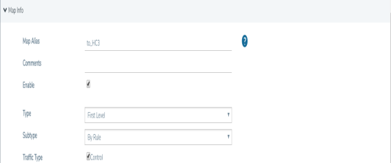
Selecting the Control option for Traffic Type of the a First Level By Rule map specifies an option for GTP applications to pass GTP control traffic (GTP-c) to all GigaSMART engines in a GTP engine group. GTP-c traffic is sent to all members of the engine group in order to replicate the session tables.
Note: In the map with the Control selected for Traffic Type, only one vport is supported.
Starting in software version 4.7, the map with the Traffic Type Control set can be edited. For example, Traffic Type Control can be added to an existing first level map, or it can be deleted from a first level map by clearing the Control checkbox for Traffic Type (refer to Figure 1: GTP Control Traffic Selected). Other editing, such as changing the Source or the Destination in the first level map is also allowed.
Starting in software version 4.7, the map with Traffic Type Control set can be edited. For example, Control can be selected in an existing first level map, or it can be deleted from a first level map by clearing Control. Other editing, such as changing the Source or the Destination in the first level map is also allowed.
To set GTP Control Traffic:
|
1.
|
From the device view, select GigaSMART > Maps > Maps and click New. |
|
2.
|
On the New Map page, select First Level and By Rule for the map type and subtype, respectively. |
|
4.
|
Configure the map and click Save when done. |
|
Figure 42
|
GTP Control Traffic Selected |
Upgrade from Earlier Release
When there is existing GTP configuration with one engine port per GigaSMART group in a pre-4.5 software version, an upgrade from that earlier software version to 4.5 or a higher release will succeed.
However in the 4.5 or higher release, you cannot convert that configuration to multiple engine ports per GigaSMART group. You must delete the configuration and reconfigure it, including the GigaSMART group, GigaSMART operation, virtual port, and maps. This is due to the need for separate maps for GTP control plane and GTP user plane traffic in 4.5 and higher releases.
Modify Engine Ports in GigaSMART Group
You can modify the engine ports in a GigaSMART group. For example, you can add an engine port to a GigaSMART group or remove an engine port from a GigaSMART group. After the change, reset all the GigaSMART line cards or modules that have engine ports configured in the GigaSMART group.
Modify vports in Map
You can modify the vport relating to the first level map with Traffic Type Control set. For example, you can change the vport configured in the map. After the change, reset all the GigaSMART line cards or modules that have engine ports configured in the vport.
Configure GTP Engine Grouping
Refer to the following examples:
GTP Engine Grouping Configuration Example
This is an example of a GTP engine group consisting of two engine ports on a GigaVUE-HC2 node. This example includes a GigaSMART operation for GTP flow filtering.
|
Task
|
Description
|
UI Steps
|
|
1
|
Configure ports as follows:
|
•
|
one network type of port. This will be used as the Source attribute in two first level maps in Task 5 and Task 6. |
|
•
|
one tool type of port for the Destination attribute in a second level flow filtering map in Task 7. |
|
•
|
one tool type of port for the Destination attribute in a shared collector map in Task 8. |
Then administratively enable the ports.
|
|
1.
|
Select Ports > Ports > All Ports |
|
2.
|
Click Quick Port Editor |
|
3.
|
Configure a network port and two tool ports. For example, select Network for port 22/3/c1 and select Tool for ports 22/3/c2 and 22/1/c3. |
|
4.
|
Select Enable for each port. |
|
6.
|
Close the Quick Port Editor. |
|
|
2
|
Configure a GigaSMART group and associate it with two GigaSMART engine port, to form the GTP engine group.
The GigaSMART group will be used in Task 5 and Task 6.
|
|
1.
|
From the device view, select GigaSMART > GigaSMART Groups > GigaSMART Groups. |
|
2.
|
Type gsg2 in the Alias field. |
|
3.
|
Click in the Port List field to add the two engine ports. |
|
|
3
|
For GTP flow filtering, configure a flow filtering GigaSMART operation and assign it to the GigaSMART group. The gsop will be used in the second level flow filtering map in Task 7.
|
|
1.
|
From the device view, select GigaSMART > GigaSMART Operations (GSOP) > GigaSMART Operation. |
|
2.
|
Type gtp_gsg2 in the Alias field. |
|
3.
|
Select gsg2 from the GigaSMART Groups list. |
|
4.
|
Select Flow Filtering from the GigaSMART Operations list. (GSOP). |
|
|
4
|
Configure a virtual port and assign it to the same GigaSMART group. This virtual port will be used as the Destination in the first level maps in Task 5 and Task 6, as the Source in the second level map in Task 7, and as the Source attribute in the shared collector map in Task 8.
|
|
1.
|
From the device view, select GigaSMART > Virtual Ports. |
|
3.
|
Type vp1 in the Alias field. |
|
4.
|
Select gsg2 from the GigaSMART Groups list. |
|
|
5
|
Create a first level map that directs GTP control traffic from the physical network port to the virtual port created in Task 4.
Note: In the rule, 2123 is GTP-c traffic.
This map, with the Traffic Type Control attribute, identifies the GTP-c control traffic needed for GTP engine grouping.
Note: The order of configuration is important. Set Traffic Type Control before any map rules.
|
|
1.
|
Select Maps > Maps > Maps. |
|
•
|
Type gtp_to_vp1-c in the Alias field |
|
•
|
Select First Level for Type |
|
•
|
Select By Rule for Subtype |
|
•
|
Select Control for Traffic Type |
|
•
|
Select 22/3/c1 for Source |
|
•
|
Select vp1 for Destination |
|
b.
|
Select Pass and Bi Directional |
|
c.
|
Select Port Destination and specify 2123 |
|
|
6
|
Create another first level map that directs GTP user traffic from the physical network port to the virtual port created in Task 5.
Note: In the rule, 2152 is GTP-u traffic.
GTP-u traffic corresponding to the same GTP-c traffic will be sent to the same virtual port.
|
|
1.
|
Select Maps > Maps > Maps. |
|
•
|
Type gtp_to_vp1 in the Alias field |
|
•
|
Select First Level for Type |
|
•
|
Select By Rule for Subtype |
|
•
|
Select Control for Traffic Type |
|
•
|
Select the network configured in Task 1 for Source |
|
•
|
Select vp1 for Destination |
|
b.
|
Select Pass and Bi Directional |
|
c.
|
Select Port Destination and specify 2123 |
|
|
7
|
Create a second level map for GTP flow filtering that takes traffic from the virtual port, applies the flow filtering GigaSMART operation, matches IMEIs and version specified by the flow rule, and sends matching traffic to a tool port.
|
|
1.
|
Select Maps > Maps > Maps. |
|
3.
|
Type from_vp1 in the Alias field. |
|
•
|
Select Second Level for Type |
|
•
|
Select Flow Filter for Subtype |
|
•
|
Select one of the tool ports configured in Task 1 for Destination. |
|
•
|
Select gtp_gsg2 for from the GSOP list.
|
|
d.
|
Specify * in the IMEI field. |
|
e.
|
Select V2 for Version. |
|
|
8
|
Add a shared collector for any unmatched traffic from the virtual port and send it to a different tool port than in Task 7.
|
|
1.
|
Select Maps > Maps > Maps. |
|
•
|
Type from_vp1_scoll in the Alias field. |
|
•
|
Select Second Level for Type |
|
•
|
Select Collector for Subtype |
|
•
|
Select the other tool port configured in Task 1 for Destination. |
|
GTP Engine Grouping Configuration Complex Example
This is a more complex example of GTP engine grouping than the previous example. This example has four engine ports on two GigaSMART line cards on the same GigaVUE-HC3 node. The GigaSMART line cards are in slots 1 and 3.
The GigaVUE-HC3 node is the cluster master of a two-node out-of-band cluster. A GigaVUE-HC2 is the standby node in the cluster.
This example includes GigaSMART operations for GTP flow filtering with load balancing, GTP flow sampling with load balancing, and GTP whitelisting. The whitelist must be associated with the GigaSMART group on the master node, the GigaVUE-HC3.
|
Task
|
Description
|
UI Steps
|
|
1
|
Configure ports on the GigaVUE-HC3 as follows:
|
•
|
One network type of port. This will be used as the Source attribute in two first level maps in Task 11 and Task 12. |
|
•
|
Twelve tool type of ports. There are four tool ports in each of three port groups used for load balancing. The port groups will be created in Task 6. |
|
•
|
Five tool type of ports for a GigaStream that will be created in Task 2. |
|
•
|
Two tool type of ports for another GigaStream that will be created in Task 2. |
Then administratively enable the ports.
|
|
1.
|
On the GigaVUE-HC3, select Ports > Ports > All Ports |
|
2.
|
Click Quick Port Editor. |
|
3.
|
Configure one network port for Task 11 and Task 12. For example, 23/2/c3. |
|
4.
|
Configure 12 tool ports for three port groups in Task 6. For example, 23/3/x1..x4 for the first port group, 23/3/x9..x12 for the second tool group, and 23/3/x13..x16 for the third port group. |
|
5.
|
Configure five tool ports for a GigaStream in Task 2. For example, 23/3/x20..x24. |
|
6.
|
Configure two tool ports for another GigaStream in Task 2. For example, 23/2/c1..c2 type tool. |
|
7.
|
Select enable for each port. |
|
9.
|
Close the Quick Port Editor. |
|
|
2
|
On the GigaVUE-HC3, configure one GigaStream using five tool ports. This will be used as the Destination attribute in the map in Task 11.
Configure another GigaStream to be used in the stack link between the GigaVUE-HC3 and GigaVUE-HC2 that will be created in Task 4.
|
|
1.
|
Select Ports > Port Groups > GigaStreams |
|
2.
|
Configure a GigaStream with five tool ports. |
|
b.
|
Type hc3-gs-1 in the Alias field. |
|
c.
|
Select Tool GigaStream. |
|
d.
|
Click in the Ports field and select the five tool ports configured in Task 1. |
|
e.
|
Click Advanced Hash Settings and use the Default setting. |
|
7.
|
Configure another GigaStream with two tool ports. |
|
b.
|
Type hc3-80g in the Alias field. |
|
c.
|
Select Tool GigaStream. |
|
d.
|
Click in the Ports field and select the two tool ports configured in Task 1. |
|
e.
|
Click Advanced Hash Settings and use the Default setting. |
|
|
3
|
Configure ports on the GigaVUE-HC2 as follows:
|
•
|
Two tool type of ports for a GigaStream that will be created in Task 4. |
|
•
|
One tool type of port that will be used as the Destination in a map in Task 11. |
|
•
|
Four tool type of ports for a GigaStream that will be created in Task 4. |
Then administratively enable the ports.
|
|
1.
|
On the GigaVUE-HC2, select Ports > Ports > All Ports |
|
2.
|
Click Quick Port Editor. |
|
3.
|
Configure two tool ports for a GigaStream in Task 4. For example, 33/2/q1..q2 |
|
4.
|
Configure one tool ports for the map in Task 11. For example,
33/3/x11. |
|
5.
|
Configure four tool ports for a GigaStream in Task 4. For example, 33/2/x20..x24. |
|
6.
|
Select Enable for each port. |
|
8.
|
Close the Quick Port Editor. |
|
|
4
|
On the GigaVUE-HC2, configure a GigaStream using two tool ports. This will be used in the stack link created in Task 5.
Configure another GigaStream using four tool ports. This will be used in the shared collector in Task 17.
|
|
1.
|
Select Ports > Port Groups > GigaStreams |
|
2.
|
Configure a GigaStream with five tool ports. |
|
b.
|
Type hc2-gs-4 in the Alias field. |
|
c.
|
Select Tool GigaStream. |
|
d.
|
Click in the Ports field and select the five tool ports configured in Task 1. For example, 33/2/x20..x25. |
|
e.
|
Click Advanced Hash Settings and use the Default setting. |
|
7.
|
Configure another GigaStream with two tool ports. |
|
b.
|
Type hc3-80g in the Alias field. |
|
c.
|
Select Tool GigaStream. |
|
d.
|
Click in the Ports field and select the two tool ports configured in Task 1. For example, 33/2/q1..q2. |
|
e.
|
Click Advanced Hash Settings and use the Default setting. |
|
|
5
|
Configure the stack link between the GigaVUE-HC2 and GigaVUE-HC3.
|
|
1.
|
Select Ports > Port Groups > Stack Links |
|
3.
|
Select Stack GigaStream. |
|
4.
|
For First Member select hc3-80g. |
|
5.
|
For Second Member select hc2-80g |
|
|
6
|
Create three port groups and specify four tool ports each, for load balancing. Also, enable load balancing on each port group.
The port groups, hc3-pg-1 and hc3-pg-2, will be used as the Destination in two second level flow sampling maps in Task 14 and Task 15.
The port group, hc3-q2x32-1-4, will be used as the Destination in a second level flow filtering map in Task 16
|
|
1.
|
Select Ports > Port Groups > All Port Groups. |
|
2.
|
Create the first port group. |
|
b.
|
Type hc3-pg-1 in the Alias field. |
|
c.
|
Select SMART Load Balancing. |
|
d.
|
Click in the Ports field and select four tool ports. For example, 23/4/x9..x12. |
|
6.
|
Create the second port group. |
|
b.
|
Type hc3-pg-1 in the Alias field. |
|
c.
|
Select SMART Load Balancing. |
|
d.
|
Click in the Ports field and select four tool ports. For example, 23/4/x13..x16 |
|
6.
|
Create the second port group. |
|
b.
|
Type hc3-q2x32-1-4 in the Alias field. |
|
c.
|
Select SMART Load Balancing. |
|
d.
|
Click in the Ports field and select four tool ports. For example, 23/4/x13..x16 |
|
|
7
|
Configure a GigaSMART group and associate it with four GigaSMART engine ports, two in slot 1 and two in slot 3, to form the GTP engine group.
The GigaSMART group will be used in Task 8, Task 9, and Task 10.
|
|
1.
|
From the device view, select GigaSMART > GigaSMART Groups > GigaSMART Groups. |
|
3.
|
Type hc3scale-4engines-slots1and3. |
|
4.
|
Click in the Port List and select the engine ports. For example,
3/1/e1,23/1/e2,23/3/e1,23/3/e2. |
Go to Task 8.
|
|
8
|
Associate the GigaSMART group to an existing GTP whitelist.
Note: The whitelist is only supported on the cluster master node, which is the GigaVUE-HC3 in this example.
|
|
1.
|
From the device view, select GigaSMART > GigaSMART Groups > GigaSMART Groups. |
|
2.
|
Under GTP Whitelist, select the alias of an existing whitelist. For example, gtp-whitelist. |
|
|
9
|
For GTP flow filtering, configure a flow filtering GigaSMART operation, specify load balancing, and assign the GigaSMART operation to the GigaSMART group. The hc3-scale-ff-lb gsop will be used in the second level flow filtering map in Task 16.
For GTP flow sampling, configure a flow sampling GigaSMART operation, specify load balancing, and assign the GigaSMART operation to the GigaSMART group. The hc3-scale-fs-lb gsop will be used in the two second level flow sampling maps in Task 15 and Task 16.
For GTP whitelisting, configure a whitelisting GigaSMART operation, and assign the GigaSMART operation to the GigaSMART group. (This GigaSMART operation is not load balanced.) The hc3-scale-wl gsop will be used in the second level whitelisting map in Task 13.
|
|
1.
|
Configure a Flow Filtering operation. |
|
a.
|
From the device view, select GigaSMART > GigaSMART Operations (GSOP) > GigaSMART Operation. |
|
c.
|
Type hc3-scale-ff-lb in the Alias field. |
|
d.
|
Select hc3scale-4engines-slots1and3 from the GigaSMART Groups list. |
|
e.
|
Select Flow Filtering from the GigaSMART Operations (GSOP) list. |
|
7.
|
Configure a Flow Sampling operation. |
|
a.
|
From the device view, select GigaSMART > GigaSMART Operations (GSOP) > GigaSMART Operation. |
|
c.
|
Type hc3-scale-fs-lb in the Alias field. |
|
d.
|
Select hc3scale-4engines-slots1and3 from the GigaSMART Groups list. |
|
e.
|
Select Flow Sampling from the GigaSMART Operations (GSOP) list. |
|
f.
|
Select Flow Sampling -GTP |
|
8.
|
Configure a Whitelisting operation. |
|
a.
|
From the device view, select GigaSMART > GigaSMART Operations (GSOP) > GigaSMART Operation. |
|
c.
|
Type hc3-scale-wl in the Alias field. |
|
d.
|
Select hc3scale-4engines-slots1and3 from the GigaSMART Groups list. |
|
e.
|
Select GTP Whitelist from the GigaSMART Operations (GSOP) list. |
|
f.
|
Select Enabled (default). |
|
|
10
|
Configure a virtual port and assign it to the same GigaSMART group. This virtual port will be used as the Destination in the first level maps in Task 11 and Task 12, as the Source in the second level maps in Task 13, Task 14, Task 15, Task 16, and as the Source in the shared collector in Task 17.
|
|
1.
|
From the device view, select GigaSMART > Virtual Ports |
|
3.
|
Type vp-hc3scale-4engines-slots1and3 in the Alias field. |
|
4.
|
Select hc3scale-4engines-slots1and3 from the GigaSMART Groups list. |
|
|
11
|
Create a first level map that directs GTP control traffic from the physical network port to the virtual port created in Task 10.
Note: In the rule, 2123 is GTP-c traffic.
This map, with the Traffic Type Control enabled, identifies the GTP-c control traffic needed for GTP engine grouping.
In addition to the virtual port, traffic is also sent to a GigaStream and a tool port.
|
|
1.
|
Select Maps > Maps > Maps. |
|
•
|
Type to_hc3_gtpc in the Alias field |
|
•
|
Select First Level for Type. |
|
•
|
Select By Rule for Subtype |
|
•
|
Select Control for Traffic Type |
|
•
|
Select a network port for the Source. For example, 23/3/q6. |
|
•
|
Select the GigaStream port hc3-gs-1, the virtual port p-hc3scale-4engines-slots1and3, and a tool port (for example, 23/7/q6) for the Destination. |
|
b.
|
Select Pass and Bi Directional. |
|
c.
|
Select Port Destination for the rule. |
|
d.
|
Enter 2123 for the port value. |
|
|
12
|
Create another first level map that directs GTP user traffic from the physical network port to the virtual port created in Task 10.
Note: In the rule, 2152 is GTP-u traffic.
GTP-u traffic corresponding to the same GTP-c traffic will be sent to the same virtual port.
|
|
1.
|
Select Maps > Maps > Maps. |
|
•
|
Type to_hc3_gtpu_1 in the Alias field |
|
•
|
Select First Level for Type. |
|
•
|
Select By Rule for Subtype |
|
•
|
Select a network port for the Source. For example, 23/7/q6. |
|
•
|
Select the virtual port vp-hc3scale-4engines-slots1and3 for the Destination. |
|
b.
|
Select Pass and Bi Directional. |
|
c.
|
Select Port Destination for the rule. |
|
d.
|
Enter 2152for the port value. |
|
c.
|
Select IPv4 Fragmentation for the rule. |
|
d.
|
Enter 2152for the port value. |
|
e.
|
Select allFragNoFirst for Value. |
|
|
13
|
Configure a second level map for GTP whitelisting, the whitelist map, that takes traffic from the virtual port, applies the whitelisting GigaSMART operation, and sends traffic to the remote GigaVUE-HC2 node through a GigaStream.
|
|
1.
|
Select Maps > Maps > Maps. |
|
•
|
Type from_hc3_wl in the Alias field |
|
•
|
Select Second Level for Type. |
|
•
|
Select By Rule for Subtype |
|
•
|
Select the virtual port vp-hc3scale-4engines-slots1and3 for the Source. |
|
•
|
Select the GigaStream hc2-gs-1 for the Destination. |
|
•
|
Select hc3-scale-wl from the GSOP list. |
|
|
14
|
Configure a second level map for GTP flow sampling. This is the first of two flow sampling maps.
This map filters for version 2. It takes traffic from the virtual port and applies the flow sampling GigaSMART operation.
Traffic flow is sampled based on the flow sampling rule in this map. Accepted packets are forwarded to load balancing port group hc3-pg-2.
|
|
1.
|
Select Maps > Maps > Maps. |
|
•
|
Type from_hc3_fs_v2 in the Alias field |
|
•
|
Select Second Level for Type. |
|
•
|
Select Flow Sample for Subtype |
|
•
|
Select the virtual port vp-hc3scale-4engines-slots1and3 for the Source. |
|
•
|
Select the port group hc3-pg-2 for the Destination. |
|
•
|
Select hc3-scale-fs-lb from the GSOP list. |
|
c.
|
Enter 60 for Percentage. |
|
d.
|
Enter 5* in the IMSI field. |
|
|
15
|
Configure a second level map for GTP flow sampling. This is the second of two flow sampling maps.
This map filters for version 1. It takes traffic from the virtual port and applies the flow sampling GigaSMART operation.
Traffic flow is sampled based on the flow sampling rule in this map. Accepted packets are forwarded to load balancing port group hc3-pg-1.
|
|
1.
|
Select Maps > Maps > Maps. |
|
•
|
Type from_hc3_fs_v1 in the Alias field |
|
•
|
Select Second Level for Type. |
|
•
|
Select Flow Sample for Subtype |
|
•
|
Select the virtual port vp-hc3scale-4engines-slots1and3 for the Source. |
|
•
|
Select the port group hc3-pg-1 for the Destination. |
|
•
|
Select hc3-scale-fs-lb from the GSOP list. |
|
c.
|
Enter 60 for Percentage. |
|
d.
|
Enter 5* in the IMSI field. |
|
|
16
|
Create a second level map for GTP flow filtering that takes traffic from the virtual port, applies the flow filtering GigaSMART operation, matches IMSIs specified by the flow rule, and sends matching traffic to load balancing port group hc3-q2x32-1-4.
|
|
1.
|
Select Maps > Maps > Maps. |
|
•
|
Type from_hc3_ff in the Alias field |
|
•
|
Select Second Level for Type. |
|
•
|
Select Flow Filter for Subtype |
|
•
|
Select the virtual port vp-hc3scale-4engines-slots1and3 for the Source. |
|
•
|
Select the port group hc3-pg-1 for the Destination. |
|
•
|
Select port group hc3-q2x32-1-4 from the GSOP list. |
|
c.
|
Enter * in the IMSI field. |
|
d.
|
Select Any for Version |
|
|
17
|
Add a shared collector for any unmatched traffic from the virtual port and send it to a GigaStream.
|
|
1.
|
Select Maps > Maps > Maps. |
|
•
|
Type s_coll_hc3 in the Alias field |
|
•
|
Select Second Level for Type. |
|
•
|
Select Collector for Subtype |
|
•
|
Select the virtual port vp-hc3scale-4engines-slots1and3 for the Source. |
|
•
|
Select GigaStream hc2-gs-4 for the Destination. |
|
Display Statistics
To display the GigaSMART Group statistics, select GigaSMART > GigaSMART Groups > Statistics.
Refer to GigaSMART Group Statistics Definitions for descriptions of the statistics.


